Window of infrared surveillance camera

a technology window, which is applied in the field of windows of infrared surveillance camera, can solve the problems of dampness in the lens portion, in the inner face of the illuminating portion, and inability to adjust the angle of the lens, and achieve excellent water tightness and air tightness, and uniform quality

Inactive Publication Date: 2010-04-01
APROTECH
View PDF5 Cites 21 Cited by
  • Summary
  • Abstract
  • Description
  • Claims
  • Application Information

AI Technical Summary

Benefits of technology

[0015]Preferably, the illumination window, the first lens window, the combining ring, and the second lens window are mutually bonded through ultrasonic melting, whereby the window according to the present invention can provide excellent watertightness and airtightness.
[0016]According to the present invention having the above structure, the second lens window is assembled in front of the first lens window through the combining ring in such a way as to be spaced apart from the first lens window, which as mounted in front of the camera module, at a predetermined interval, whereby the sealed air layer, which is the insulating layer, is formed between the first lens window and the second lens window. Accordingly, even though there is the difference in temperature between the inside and the outside of the surveillance camera due to heating of the devices by the long time operation of the surveillance camera, the inner face of the first lens window does not get damp due to a dew condensation.
[0017]Finally, since the window of the infrared surveillance camera according to the present invention has a double lens window structure mounted in front of the camera module and provides an insulating function owing to the sealed air layer formed between the first and second lens windows, it does not get damp even though there is the difference in temperature between the inside and the outside of the surveillance camera due to heating of the devices, whereby the present invention can continuously provide images of uniform quality.

Problems solved by technology

However, in case of the window of the single window structure, when there occurs difference in temperature between the outside and inside of the camera due to heating of devices by a long time operation, inner faces of the illuminating portion 132 and the lens portion 134 get damp.

Method used


Image

  • Window of infrared surveillance camera
  • Window of infrared surveillance camera
  • Window of infrared surveillance camera

Examples


Embodiment Construction

[0023]Reference will be now made in detail to the preferred embodiment of the present invention with reference to the attached drawings.

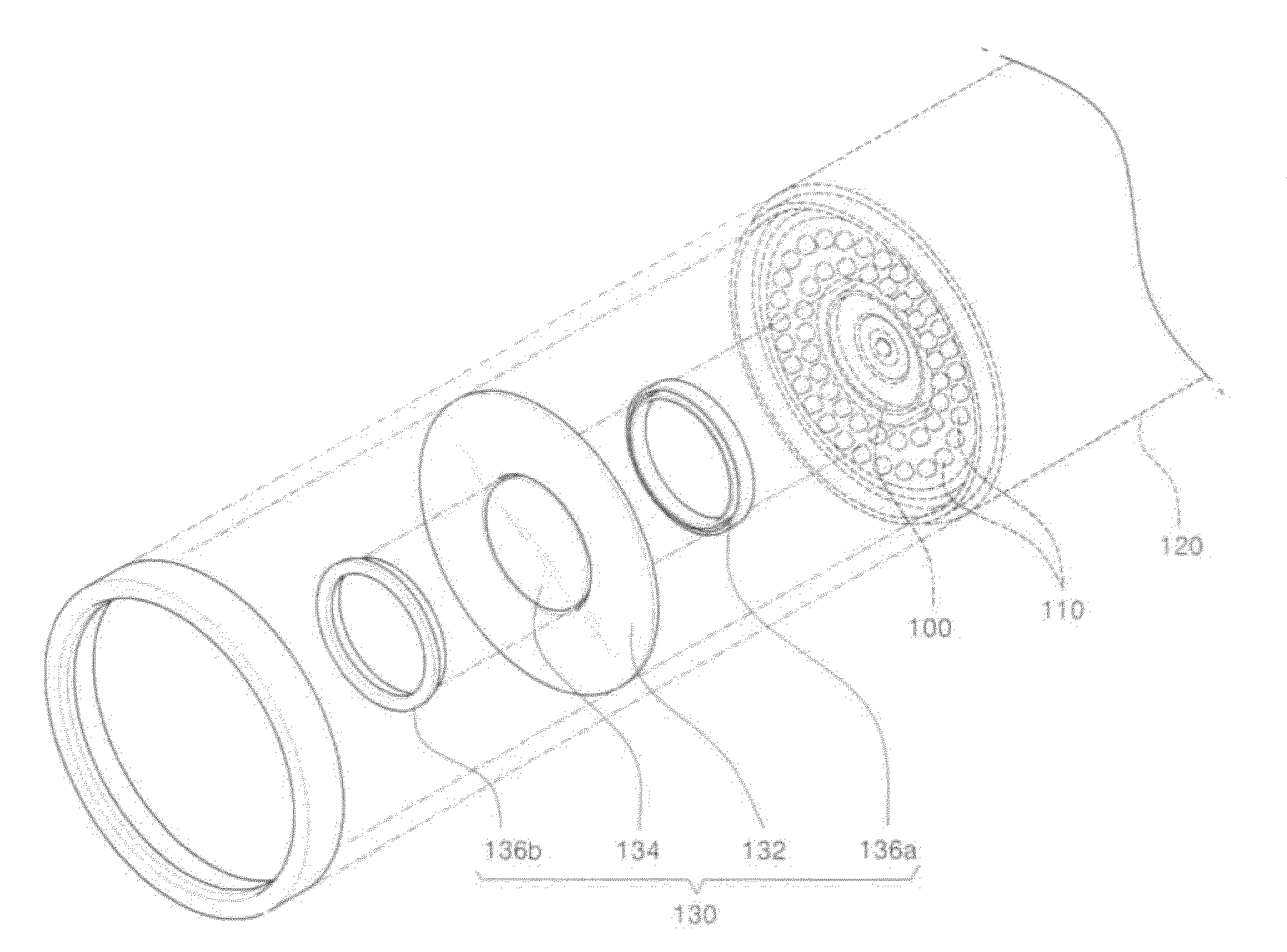
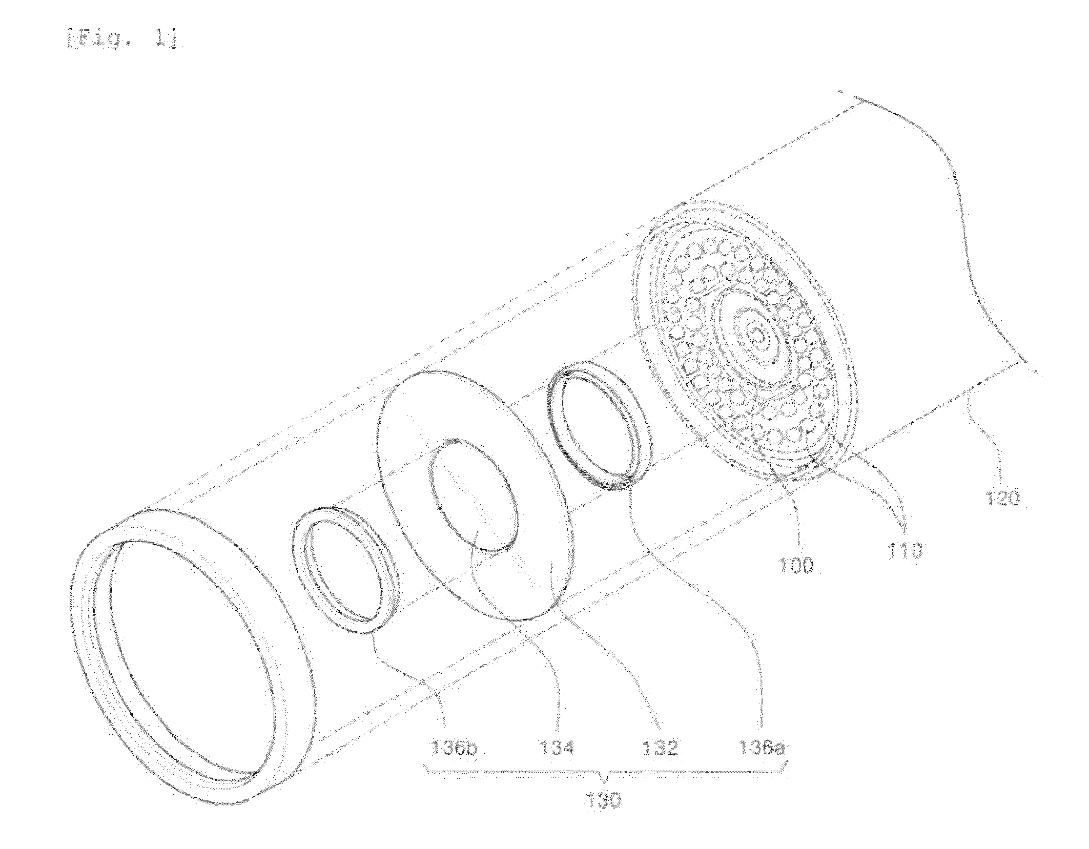
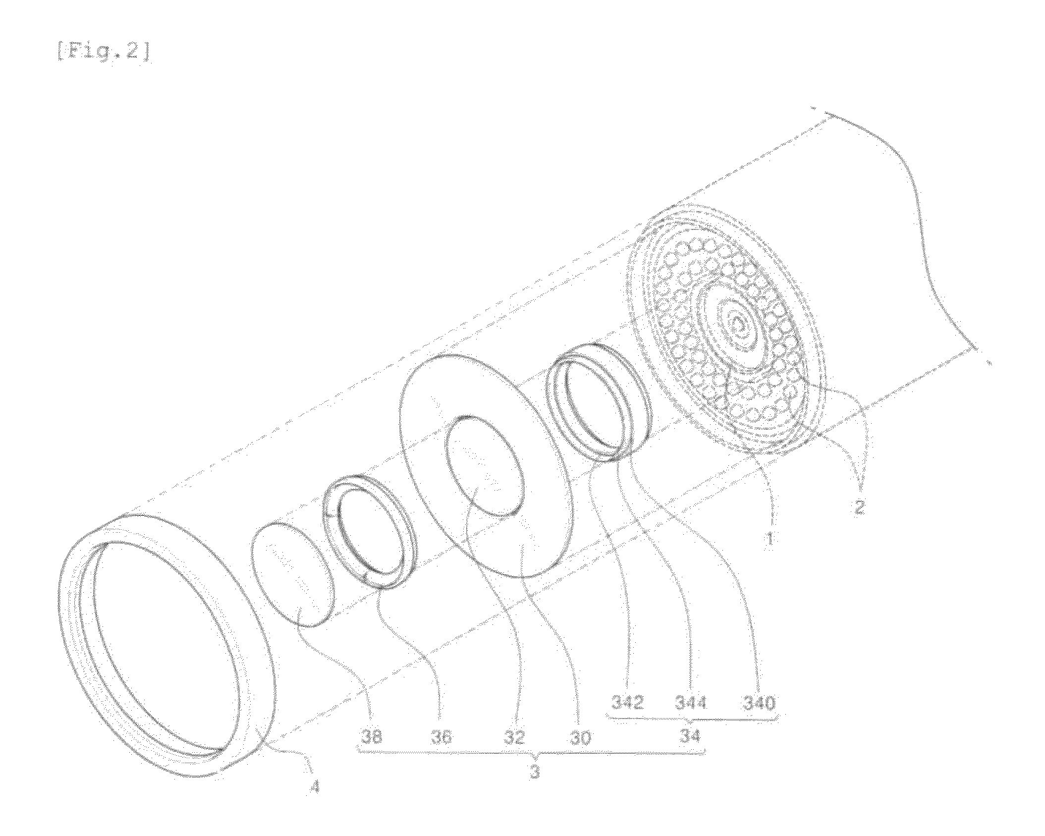
[0024]FIG. 2 is an exploded perspective view of a window of an infrared surveillance camera according to the present invention, FIG. 3 is a sectional view showing a combined state of the window of FIG. 2, and FIG. 4 is a perspective view, in section, of a combining ring shown in FIGS. 2 and 3.

[0025]As shown in the drawings, a window 3 of an infrared surveillance camera according to the present invention includes an illumination window 30, a first lens window 32, an intercepting member 34, a combining ring 36, and a second lens window 38. The second lens window 38 is assembled in front of the first lens window 32 through the combining ring 36 in such a way as to be spaced apart from the first lens window 32 at a predetermined interval, so that a sealed air layer 37, which is an insulating space, is formed between the first lens window 32 end the seco...


PUM


Abstract

Disclosed therein is a window of an infrared surveillance camera, which can prevent that the window gets damp even though there is a difference in temperature between the inside and the outside of the surveillance camera due to a long time operation of the surveillance camera. The window includes: an illumination window mounted on a light path in front of an IR LED arranged around a camera module; a first lens window formed separately from the illumination window and mounted on an image introducing path in front of a lens of the camera module; an intercepting member having an assembly face where the illumination window and the first lens window are airtightly and closely combined with each other, the intercepting member being mounted between the illumination window and the first lens window for preventing that infrared rays are introduced from a light irradiation zone, where the IR LED is mounted, to a photograph zone, where the camera module is mounted; a combining ring assembled in front of the intercepting member for simultaneously restricting the illumination window and the first lens window; and a second lens window assembled to the combining ring and spaced apart from the first lens window through the combining ring so that a sealed air layer is formed between the second lens window and the first lens window.

Description

BACKGROUND OF THE INVENTION [0001]1. Field of the Invention[0002]The present invention relates to a window of an infrared surveillance camera, and more particularly, to a window of an infrared surveillance camera, which can prevent that the window gets damp due to a difference in temperature between the inside and the outside of the surveillance camera during an operation of the surveillance camera.[0003]2. Background Art[0004]In general, a surveillance camera is a photographing device, which takes a photograph of a specific place or thing, which is at a long distance and sends a captured image to a CCTV (Closed Circuit Television), so that a user can check conditions of the captured place or thing without going to the captured scene. The surveillance camera is generally installed at a specific place with a specific purpose, namely, in order to monitor the place where burglaries or accidents may occur or to check an operational state or a process flow of a machine.[0005]The surveill...

Claims


Application Information

Patent Timeline
Patent Type & Authority Applications(United States)
IPC IPC(8): H04N7/18G03B17/00G03B30/00H04N5/33
CPCH04N5/2256G08B13/19626H04N23/56H04N7/18
Inventor LEE, HAN MO
Owner APROTECH
Why Eureka
Try Eureka