Steel bar bundling mechanical hand and special buckle element thereof

A technology of manipulators and steel bars, which is applied to the parts of strapping machines, strapping materials, flexible and slender components, etc., can solve the problems of restrictions on the popularization and application of strapping machines, low recycling rate of wire coils, and increased use costs, etc., to achieve the goal of using Wide range, safe use, fast effect

Inactive Publication Date: 2012-03-28
孙激扬 +1
View PDF9 Cites 8 Cited by
  • Summary
  • Abstract
  • Description
  • Claims
  • Application Information

AI Technical Summary

Problems solved by technology

[0002] Currently, the strapping machines mainly used in the market are Japanese machines and imitation machines from other manufacturers. advantage, but it also has very serious defects in practical application, because the floor reinforcement on the construction site is all attached to the formwork before binding, but the existing binding machine must require the distance between the reinforcement and the formwork when binding the reinforcement. There is a certain distance between them, otherwise the jaws and binding wires cannot pass through the steel bars, and the binding volume of floor steel bars in engineering buildings accounts for more than 60%, so the popularization and application of existing binding machines is greatly restricted. In addition, the existing binding The machine needs to bind a node with a wire length of more than 36cm, which is a waste for bundling small-sized steel bars, and the recycling rate of the coil after the wire is used up is also very low. These two situations indirectly increase the cost of use.
In addition, the working principle of this strapping machine is completed through two steps before and after wire feeding and winding, and the speed is also subject to certain restrictions.

Method used


Image

  • Steel bar bundling mechanical hand and special buckle element thereof
  • Steel bar bundling mechanical hand and special buckle element thereof
  • Steel bar bundling mechanical hand and special buckle element thereof

Examples


Embodiment

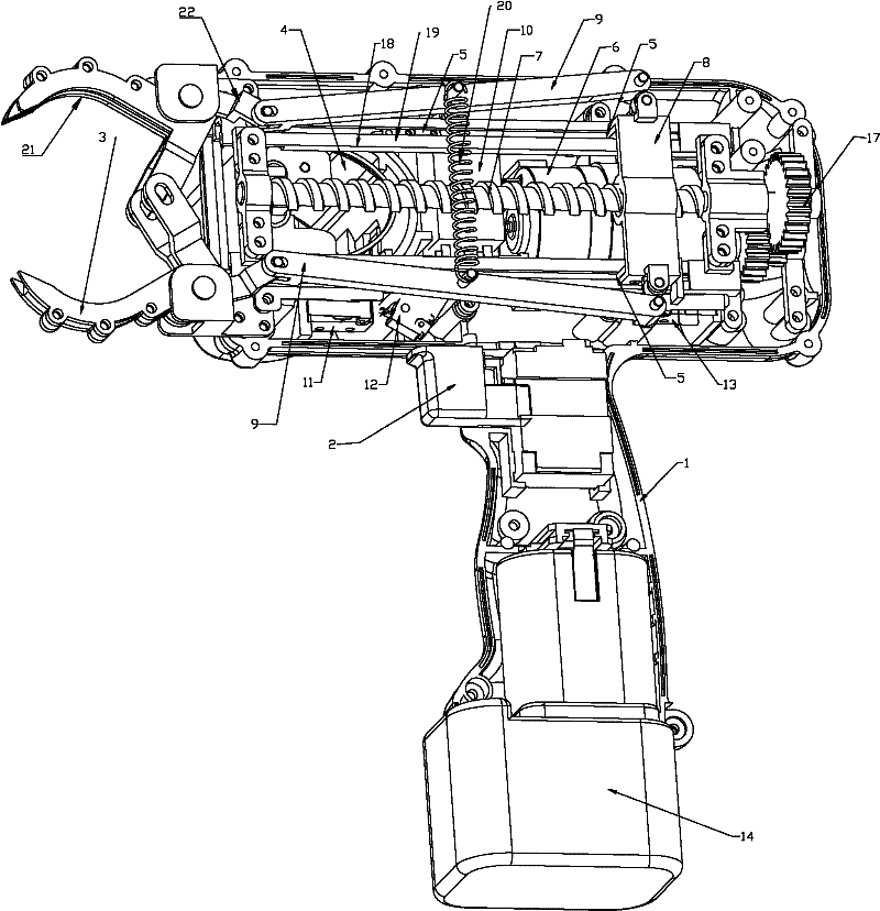
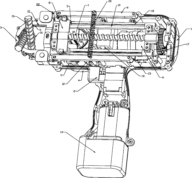
[0040] like figure 1 Shown: a steel bar binding manipulator, including a body 1, is characterized in that it is composed of the following parts: a holding mechanism installed on the outer end of the body to hold the binding fastener, and a loading mechanism installed on the inside of the body to bind the fastener, and The sending mechanism of the binding fastener that pushes out the binding fastener from the loading mechanism and sends it into the holding mechanism, and the power mechanism that drives the sending mechanism to move back and forth by rotation, and makes the holding mechanism close and open connecting rod drive mechanism.

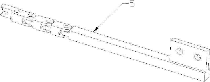
[0041] The sending device of the binding fastener is composed of a gear device 17, a guide screw 7, a screw sleeve 8, two upper and lower guide rods 19, and two upper and lower chain pushers 5. The gear device 17 is installed behind the body 1 end, the rear end of the guide screw 7 is connected to the gear device 17, the front end is fix...


PUM


Abstract

The invention discloses a steel bar bundling mechanical hand and a used buckle element. The mechanical hand comprises a machine body and consists of the following parts: a holding mechanism, a loading mechanism of a bundling buckle element, a sending mechanism of the bundling buckle element, a motive power mechanism and a connecting rod driving mechanism, wherein the holding mechanism is arrangedat the outer end of the machine body and is used for holding the bundling buckle element, the loading mechanism of the bundling buckle element is arranged inside the machine body, the sending mechanism pushes the bundling buckle element out of the loading mechanism and sends the bundling buckle element into the holding mechanism, the motive power mechanism drives the sending mechanism to forwardsand backwards move through motive power, the connecting rod driving mechanism makes the holding mechanism close and open, the buckle element comprises an annular main body, both ends of the main bodyare provided with barbs capable of being mutually buckled, and the back ends of the barbs are provided with outwards projected shoulder parts. The steel bar bundling mechanical hand and the buckle element have the advantages that the use range is wider, and steel bars pasting the ground can also be bundled. An iron wire disc is not needed, no excess joints are left, the iron wires are saved, and the use cost is reduced. No projected joints are left at the bundling point, the people scratch injury phenomenon can not be generated, the use is safe, the bundling steps are simple, and the bundlingis fast.

Description

technical field [0001] The invention relates to a binding machine device and a binding fastener, in particular to a steel bar binding manipulator for binding steel bars in concrete construction and a special binding fastener. Background technique [0002] At present, the strapping machines mainly used in the market are Japanese machines and imitation machines of other manufacturers. This strapping machine has great advantages compared with manual labor in terms of speed and strapping effect, but it also has serious problems in practical applications. Because the floor reinforcement on the construction site is attached to the formwork before binding, but the existing binding machine must require a certain distance between the reinforcement and the formwork when binding the reinforcement, otherwise the jaws and wires cannot pass through the reinforcement , and the binding amount of floor steel bars accounts for more than 60% in engineering buildings, so the popularization and ...

Claims


Application Information

Patent Timeline
Patent Type & Authority Applications(China)
IPC IPC(8): B65D63/06B65B13/02B65B13/18
Inventor 陈志刚
Owner 孙激扬
Why Eureka
Try Eureka