Auto-focusing method and device

a technology of auto-focusing and optical measurement, applied in the direction of optical elements, fluorescence/phosphorescence, instruments, etc., can solve the problems of not preserving intensities, difficult implementation, and not applicable to quantitative fluorescence microscopy applications, and achieve fast auto-focusing techniques, easy identification, and the effect of avoiding bleaching or photo-damage of samples

Inactive Publication Date: 2005-06-09
YEDA RES & DEV CO LTD
View PDF15 Cites 115 Cited by
  • Summary
  • Abstract
  • Description
  • Claims
  • Application Information

AI Technical Summary

Benefits of technology

[0023] The technique of the present invention provides for inspecting a sample supported on a plate-like substrate transparent with respect to incident radiation. The main idea of the present invention consists of detecting an in-focus position of the substrate's surface supporting the sample by continuously varying the relative distance between the sample and an objective (generally, focusing optics) along the optical axis of the objective so as to scan the substrate's thickness (height), while continuously directing incident radiation towards the substrate through the objective and detecting reflections of the incident radiation collected by said objective. This technique enables the sequential detection of two reflected intensity peaks, wherein the first detected peak corresponds to the in-focus position of the surface of the substrate closer to the objective, and the second detected peak corresponds to the in-focus position of the other opposite surface of the substrate, which carries the sample. This technique thus provides for a very fast in-focus positioning of the sample-carrying surface.
[0027] (c) continuously detecting reflected components of the electromagnetic radiation collected through said objective lens arrangement, said detected reflected components being characterized by a first intensity peak corresponding to an in-focus position of said opposite surface of the substrate, and a second intensity peak spaced in time from the first intensity peak and corresponding to an in-focus position of said sample-supporting surface of the substrate, thereby enabling imaging of the sample when in the in-focus position of the sample-supporting surface of the substrate.
[0031] Preferably, the displacement of the focal plane relative to the substrate is carried out with a higher speed until the first intensity peak is detected, and is then slowed until the second intensity peak is detected. Thus, a very fast approach to focus can be achieved from afar, but no mechanical overshoot will be experienced when reaching the in-focus position of the substrate's surface.
[0044] The present invention provides for a very fast auto-focusing technique. The focus swept time until the in-focus position of the sample-supporting surface is reached, depends practically on the time needed for mechanical focus adjustment, since the whole process is performed by closed-loop hardware control, e.g., a piezo-mounted objective having a millisecond response. The in-focus signal (intensity peak) is strong, falling sharply with the movement of the respective surface away from the in-focus position, and has a well defined magnitude which is independent on the sample and therefore can easily be identified by a very fast focal sweep, without being disturbed by weak signals associated with the sample. The magnitude of the signal is known (from a suitable calibration procedure) and provides for identifying the in-focus position of the two opposite surfaces of the substrate.
[0045] By using red (or infrared) light in the focusing apparatus, bleaching or photo-damage of the sample is avoided. The technique is therefore ideally suitable for inspecting live samples, such as GFP tagged cells. The method of the present invention is also suitable for thick samples, where no focal height of any absolute sense can be defined. The auto-focusing method of the invention sets on the substrate-slide surface forming the lower limit (closest to the objective) Z-focus of the 3D sample. The system offers a very high speed factor in the imaging and analysis of three-dimensional samples, since the exact edge of the cell volume (sample-supporting surface of the substrate) is determined avoiding the need for over-scanning focal planes.
[0048] The method of the present invention is applicable for transparent samples, such as biological cells. No reflection, scattering or fluorescence from the sample itself is used. The method is independent on the microscope imaging mode or sample type, and is effective even when some fields in the specimen do not have cells or have cells that are not labeled. Being an imaging-independent method, the present invention can be used with various imaging modes (phase, Nomarskii Differential Interference Contrast (DIC) or fluorescence). The present invention can utilize air objectives, as well as the highest NA immersion objectives. The present invention as described below uses confocality principles, but it should be understood that it is operable with wide-field microscopes as well, without affecting the imaging optical path.

Problems solved by technology

These techniques require calibrations and adjustments to match auto-focusing and imaging optical systems, and are hard to implement, especially when the imaging optics has variable magnification.
Additionally, these techniques are not preserving intensities, and therefore are not applicable for quantitative fluorescence microscopy applications.
Such accuracy is far beyond the tolerance of the bottom surfaces of multi-well dishes, and even typical high-performance XYZ stages cannot scan distances of about 10 cm in the XY plane while keeping the Z coordinate within the above tolerances.
However, this approach has several inherent problems: 1.
The process is slow.
Yet, there is no scheme that will map the distance from the focus into any evaluation parameter with smooth dependence displaying a single minimum over three orders of magnitude range of defocusing.
Glass slides or plastic well bottoms are a fraction of a millimeter thick and may often cause auto-focus devices based on maximal sharpness to focus at the wrong side of the sample substrate.
However, image-based focusing is not applicable to fluorescent microscopy, where repeated imaging may cause bleach and phototoxicity.
Focusing methods that evaluate fluorescence are therefore not applicable for such screens.

Method used


Image

  • Auto-focusing method and device
  • Auto-focusing method and device
  • Auto-focusing method and device

Examples


Embodiment Construction

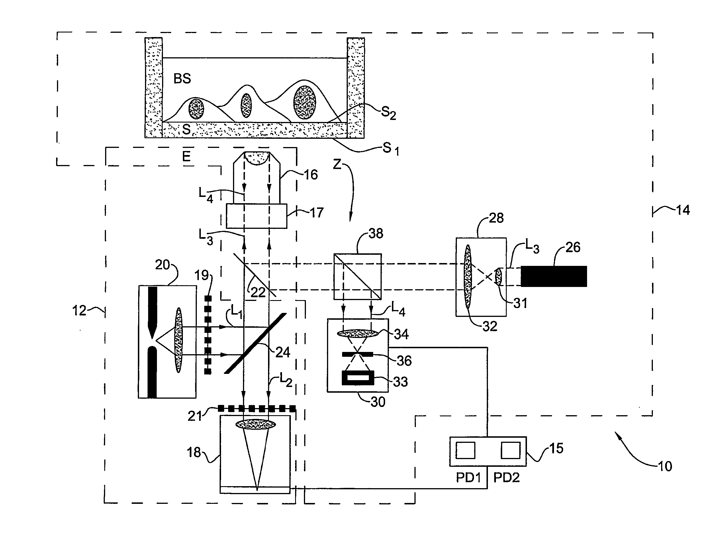
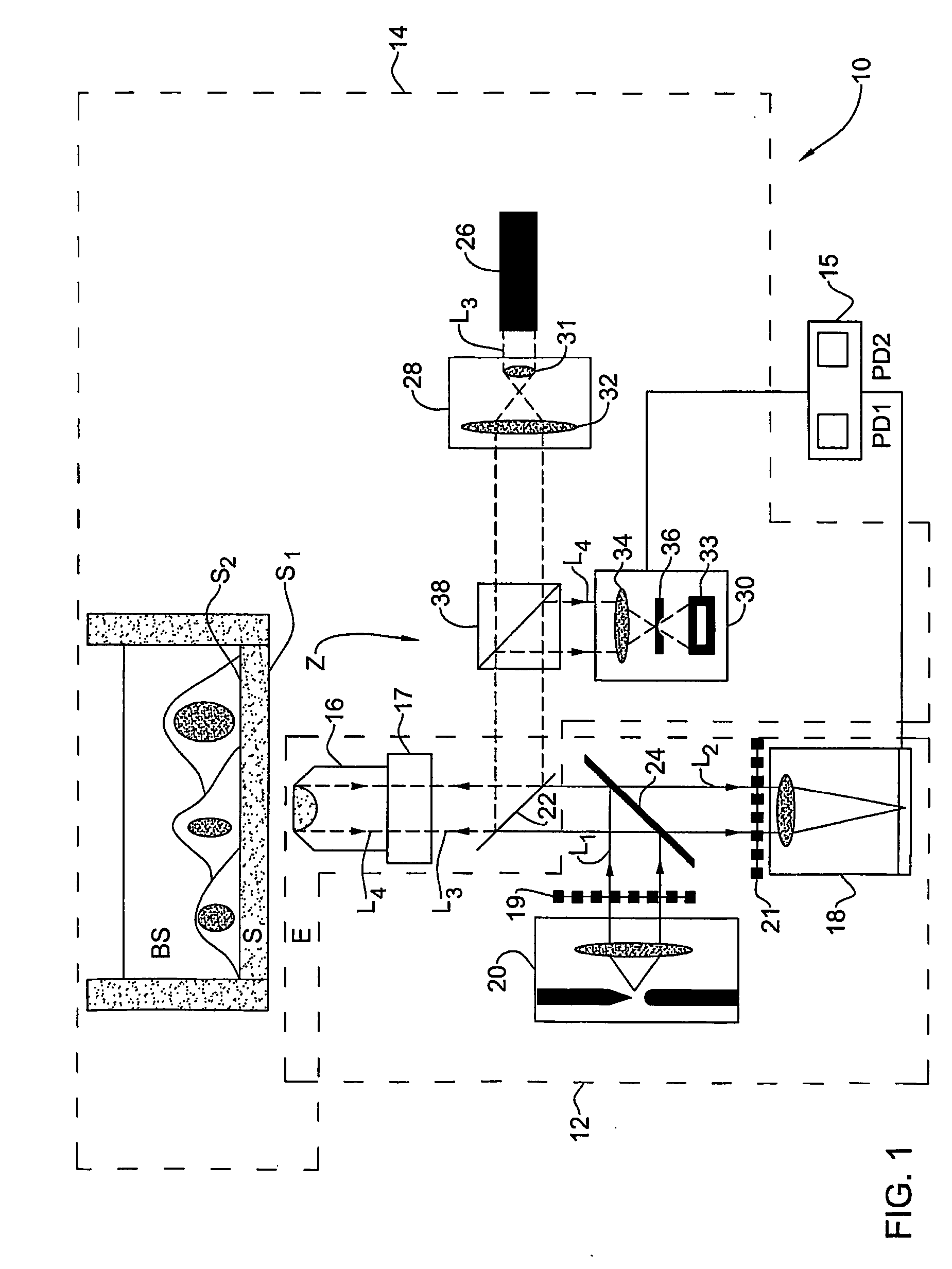
[0062] Referring to FIG. 1, there is illustrated an imaging system 10 for acquiring images of a sample, a biological sample BS in the present example. The system comprises such main constructional parts as an imaging device 12 and an auto-focusing device 14 associated with a control unit 15 connectable to the elements of the auto-focusing and imaging devices, as will be described more specifically further below. As shown, the biological sample BS (typically a sample chamber including a buffer layer in which cells are grown) is located on the surface S2 of a substrate S (glass / plastic slide). The system 10 is located at the opposite surface S1 of the substrate. The substrate is supported on a stage (not shown) movable in a plane perpendicular to the Z-axis.

[0063] The control unit 15 comprises a processing utility PD1 operable to process data coming from the auto-focusing device 14 to generate a focusing signal indicative of the in-focus position of the sample-carrying surface for ac...


PUM

PropertyMeasurementUnit
heightaaaaaaaaaa
transparentaaaaaaaaaa
semi-transparentaaaaaaaaaa

Abstract

An auto-focusing method and device are presented for determining an in-focus position of a sample supported on a substrate plate made of a material transparent with respect to incident electromagnetic radiation. The method utilizes an optical system capable of directing incident electromagnetic radiation towards the sample and collecting reflections of the incident electromagnetic radiation that are to be detected. A focal plane of an objective lens arrangement is located at a predetermined distance from a surface of the substrate, which is opposite to the sample-supporting surface of the substrate. A continuous displacement of the focal plane relative to the substrate along the optical axis of the objective lens arrangement is provided, while concurrently directing the incident radiation towards the sample through the objective lens arrangement to thereby focus the incident radiation to a location at the focal plane of the objective lens arrangement. Reflected components of the electromagnetic radiation to a location objective lens arrangement are continuously detected. The detected reflected components are characterized by a first intensity peak corresponding to an in-focus position of said opposite surface of the substrate, and a second intensity peak spaced in time from the first intensity peak and corresponding to an in-focus position of said sample-supporting surface of the substrate. This technique enables imaging of the sample when in the in-focus position of the sample-supporting surface of the substrate.

Description

FIELD OF THE INVENTION [0001] This invention is generally in the field of optical measurement / inspection techniques and relates to an auto-focus method and device, and an imaging system utilizing the same for use with optical microscopy. The invention is particularly useful for the microscope inspection of fluorescently labeled biological specimens on transparent slides. BACKGROUND OF THE INVENTION [0002] Auto focusing is an essential feature in many automated inspection fields such as the chip industry, biomedical research, data reading / recording in optical information carriers, etc. [0003] Auto-focusing techniques used in the inspection / measurement of such structures as semiconductor wafers typically utilize an optical system separated from an imaging optics, which projects a light pattern (e.g., spots, lines, etc.) on the wafer and optimizes the image of this pattern (by using intensity contrast or displacement). Such techniques are applicable only for long working distance micro...

Claims


Application Information

Patent Timeline
Patent Type & Authority Applications(United States)
IPC IPC(8): G01N21/64G02B7/36G02B7/38G02B21/24
CPCG01N21/6458G02B7/36G02B21/244G02B7/38G02B7/365
Inventor KAM, ZVIGEIGER, BENJAMIN
Owner YEDA RES & DEV CO LTD
Why Eureka
Try Eureka