Engine balance shaft oil pressure releasing structure

A balance shaft and engine technology, applied in the direction of controlling lubricant pressure, etc., can solve problems such as unreliable work of the balance shaft, damage to the balance shaft mechanism, loose bearings, etc., to improve driving comfort, avoid loose bearings, and extend service life The effect of longevity

Active Publication Date: 2012-03-28
力帆科技(集团)股份有限公司
View PDF6 Cites 7 Cited by
  • Summary
  • Abstract
  • Description
  • Claims
  • Application Information

AI Technical Summary

Problems solved by technology

[0003] The purpose of the present invention is to solve the problem that the oil pressure in the first bearing on the right side of the balance shaft is too high, resulting in loose bearings, damage to the balance shaft mechanism, and unreliable operation of the balance shaft by providing an oil drain channel on the right side of the balance shaft

Method used


Image

  • Engine balance shaft oil pressure releasing structure
  • Engine balance shaft oil pressure releasing structure
  • Engine balance shaft oil pressure releasing structure

Examples


Embodiment Construction

[0009] Below in conjunction with accompanying drawing and embodiment the present invention will be further described:

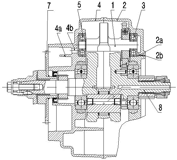
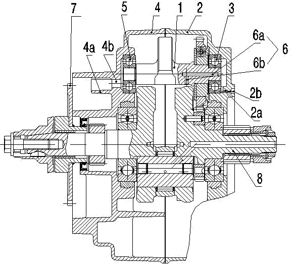
[0010] figure 2 The shown engine balance shaft unloading oil pressure structure consists of a balance shaft 1, a right crankcase 2, a first bearing 3 installed on the right crankcase 2, a left crankcase 4, and a second bearing installed on the left crankcase 4 5. Composition of starting gear 7, crankshaft 8, etc. The right side of the balance shaft 1 is journaled on the first bearing 3 , and the left side of the balance shaft 1 is journaled on the second bearing 5 . The balance shaft 1 is set parallel to the crankshaft 8, the gear on the crankshaft 8 meshes with the gear on the balance shaft 1, the crankshaft 8 drives the balance shaft 1 to rotate together, and a starting gear 7 is installed on the left side of the crankshaft 1, and the starting gear 7 is set on The left side of the left crankcase 4. The right side of the right crankcase 2 is provided wit...


PUM


Abstract

The invention discloses an engine balance shaft oil pressure releasing structure. According to the structure, a right shaft neck of a balance shaft (1) is supported on a first bearing (3) of a right crank case (2), a left shaft neck of the balance shaft (1) is supported on a second bearing (5) of a left crank case (4), the right half part of the balance shaft (1) is provided with a horizontal oilhole (6a) and a vertical oil hole (6b) which are communicated with each other, and an oil drainage channel (6) composed of the horizontal oil hole (6a) and the vertical oil hole (6b) can be led to the interior of the right crank case (2) through the first bearing (3). The structure can be used for avoiding the problems of loosened bearing and damaged balance shaft mechanism and the like caused bytoo high oil pressure of the first bearing, thus the working stability of the balance shaft can be obviously improved.

Description

technical field [0001] The invention relates to the technical field of engines, in particular to an oil pressure relief structure of an engine balance shaft. Background technique [0002] In order to reduce the vibration of the engine, a balance mechanism is usually arranged in the crankcase. like figure 1 As shown, the right journal of the engine balance shaft 1 is supported on the first bearing 3 of the right crankcase 2, and the left journal is supported on the second bearing 5 of the right crankcase 4. The balance shaft 1 is parallel to the crankshaft 8 Set, the gear on the crankshaft 8 meshes with the gear on the balance shaft 1, and the crankshaft 8 drives the balance shaft 1 to rotate together, and the starting gear 7 is also housed on the left side of the crankshaft 8. On the left side of the left crankcase 4, an oil baffle plate 4a and a horizontal through hole 4b are arranged, and the lubricating oil splashed during the rotation of the starter gear 7 is introduce...

Claims


Application Information

Patent Timeline
Patent Type & Authority Applications(China)
IPC IPC(8): F01M1/16
Inventor 田亚平程志明
Owner 力帆科技(集团)股份有限公司
Why Eureka
Try Eureka