High-precision flow regulating valve with lock

A flow regulating valve, high-precision technology, applied in the direction of valve details, safety valves, balance valves, etc., can solve the problems of inconvenient measurement and control of flow regulating valves, affecting the accuracy of flow value reading, and poor flow regulation performance. Achieve the effect of improving flow regulation accuracy, high-precision regulation, and ensuring accuracy

Active Publication Date: 2012-03-28
ZHEJIANG DUNAN INTELLIGENT CONTROL TECH CO LTD
View PDF6 Cites 6 Cited by
  • Summary
  • Abstract
  • Description
  • Claims
  • Application Information

AI Technical Summary

Problems solved by technology

[0002] There are many manual flow control valves on the market now. The sealing form between the disc in the valve body and the sealing surface on the throttle port is a simple flat seal. There is no relationship between the flow value of this flow control valve and the displacement of the disc. There is no linear relationship, the flow regulation performance is very poor, and it is not convenient to measure and control the flow of the flow regulating valve; at the same time, this kind of flow regulating valve has no locking device, which is easily affected by misoperation by unrelated personnel, and it is difficult to effectively control the flow of the pipeline. control
[0003] There are also some lockable high-precision flow regulating valves with flow display. The flow display method is that the inner ring is provided with a scale, and the flow value is indicated by the position of the bottom edge of the outer ring cap and the position of the inner ring scale. , the outer ring rotates with the valve stem and can slide up and down, so when reading the flow value, the line of sight must be placed at the level of the outer ring, otherwise it will affect the accuracy of the flow value reading

Method used


Image

  • High-precision flow regulating valve with lock
  • High-precision flow regulating valve with lock
  • High-precision flow regulating valve with lock

Examples


Embodiment Construction

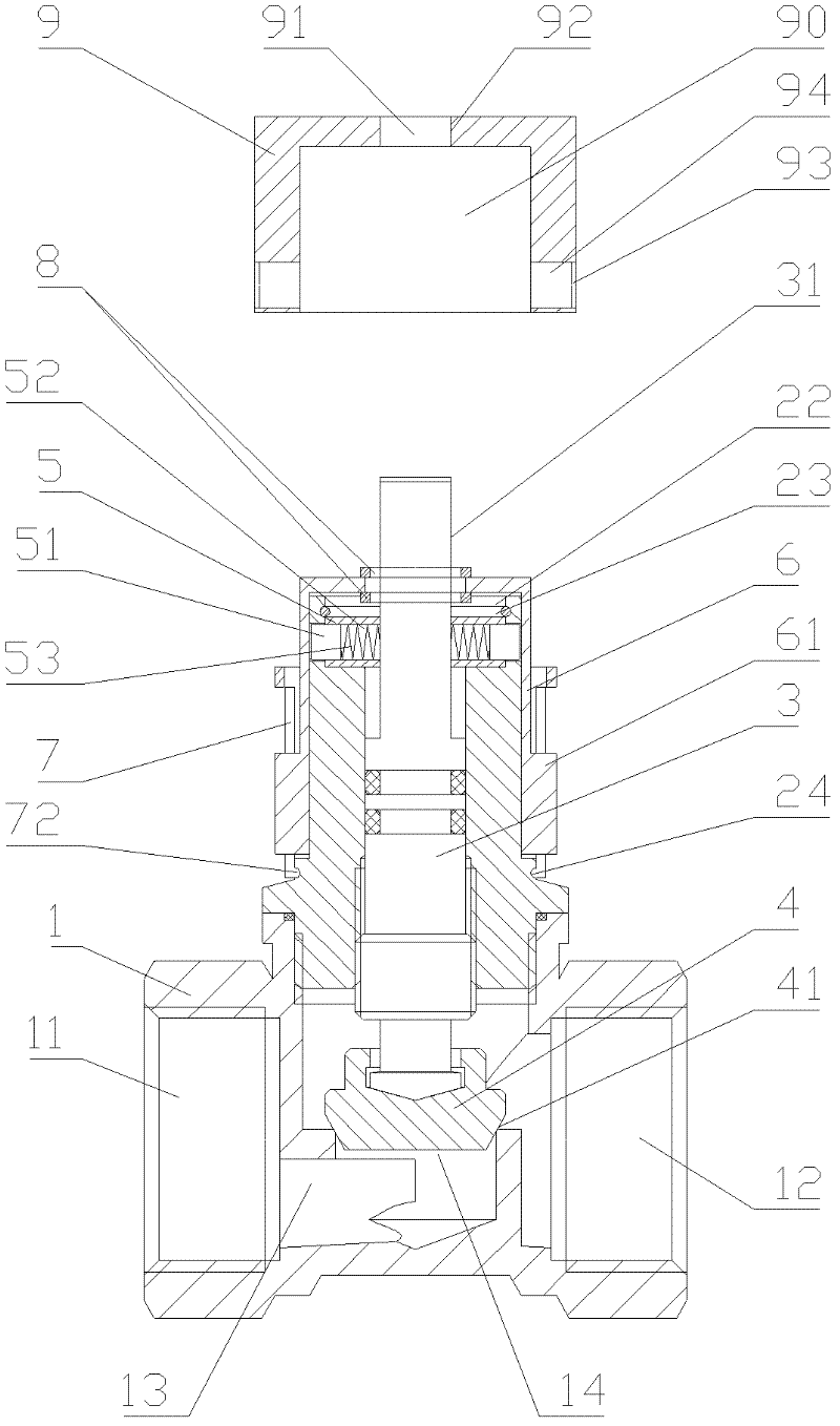
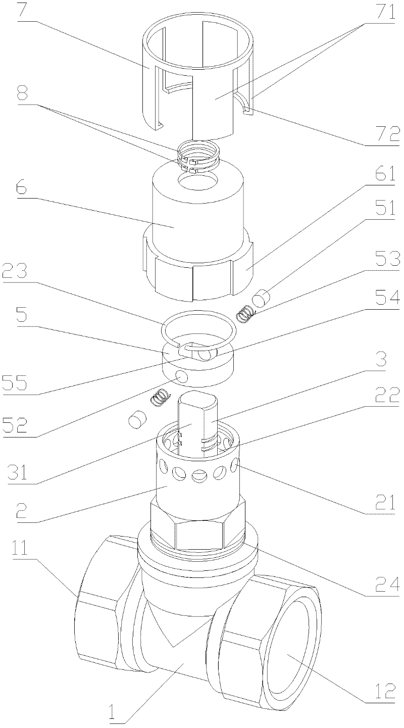
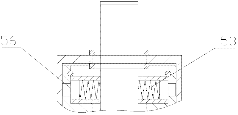
[0023] Such as figure 1 with 2 Shown is a structural schematic diagram of an embodiment of the present invention, a high-precision flow regulating valve with a lock, including a valve body 1, a valve cover 2 and a valve stem 3, and the two ends of the valve body are respectively provided with an inlet 11 and an outlet 12, and through the The valve cavity 13 in the body is connected, and the valve cavity is provided with a throttle port 14. The bonnet is sealed and connected to the valve body. The valve stem is sealed and installed in the bonnet and moves up and down along the bonnet. 4 Corresponds to the throttle port and opens or closes the throttle port as the valve stem moves up and down. The bottom of the valve flap is provided with a tapered ring surface 41 that matches with the throttle port and has a larger diameter and a smaller diameter. The upper end of the valve stem and the valve cover There is a locking assembly that locks the position of the valve stem and unloc...


PUM


Abstract

The invention discloses a high-precision flow regulating valve with a lock, which comprises a valve body, a valve cover and a valve stem, wherein two ends of the valve body are respectively provided with an inlet and an outlet, the inlet and the outlet can be communicated through a valve cavity in the valve body, the interior of the valve body is provided with a throttle, the valve cover is tightly connected with the valve body, the valve stem tightly penetrates in the valve cover and can move up and down along the valve cover, the lower end of the valve stem is provided with a valve clack which corresponds to the throttle and can open or close the throttle with the up-and-down movement of the valve stem, the bottom of the valve clack is provided with a tapered ring surface which is matched with the throttle and is provided with a larger diameter on the top and a smaller diameter at the bottom, a lock assembly which can lock the position of the valve stem and can be unlocked by the corresponding key is arranged between the top end of the valve stem and the valve cover, and a flow display component which can display the flow of the throttle in real time is arranged on the valve cover. The high-precision flow regulating valve with a lock provided by the invention has a simple structure, is convenient to manufacture, has linearly flow-regulating and locking functions and can realize high-precision flow regulation.

Description

technical field [0001] The invention relates to a throttling element, in particular to a high-precision flow regulating valve with a lock. Background technique [0002] There are many manual flow control valves on the market now. The sealing form between the disc in the valve body and the sealing surface on the throttle port is a simple flat seal. There is no relationship between the flow value of this flow control valve and the displacement of the disc. There is no linear relationship, the flow regulation performance is very poor, and it is not convenient to measure and control the flow of the flow regulating valve; at the same time, this kind of flow regulating valve has no locking device, which is easily affected by misoperation by unrelated personnel, and it is difficult to effectively control the flow of the pipeline. control. [0003] There are also some lockable high-precision flow regulating valves with flow display. The flow display method is that the inner ring is...

Claims


Application Information

Patent Timeline
Patent Type & Authority Applications(China)
IPC IPC(8): F16K17/20F16K35/16F16K37/00
Inventor 周云兵钱金明赵明祥
Owner ZHEJIANG DUNAN INTELLIGENT CONTROL TECH CO LTD
Why Eureka
Try Eureka