A pneumatic all-inclusive ball valve

A technology of wrapping balls and spherical shells, applied in the field of pneumatic all-inclusive ball valves, which can solve the problems of inconvenient disassembly and repair of pneumatic all-inclusive ball valves and low accuracy, and achieve the effect of easy repair of the valve interior and high flow adjustment accuracy

Active Publication Date: 2019-11-29
拓姆菲阀门科技(安徽)有限公司
View PDF1 Cites 0 Cited by
  • Summary
  • Abstract
  • Description
  • Claims
  • Application Information

AI Technical Summary

Problems solved by technology

However, the pneumatic all-inclusive ball valve is not easy to disassemble and repair, and the accuracy of adjusting the flow is low

Method used


Image

  • A pneumatic all-inclusive ball valve
  • A pneumatic all-inclusive ball valve
  • A pneumatic all-inclusive ball valve

Examples


specific Embodiment approach 1

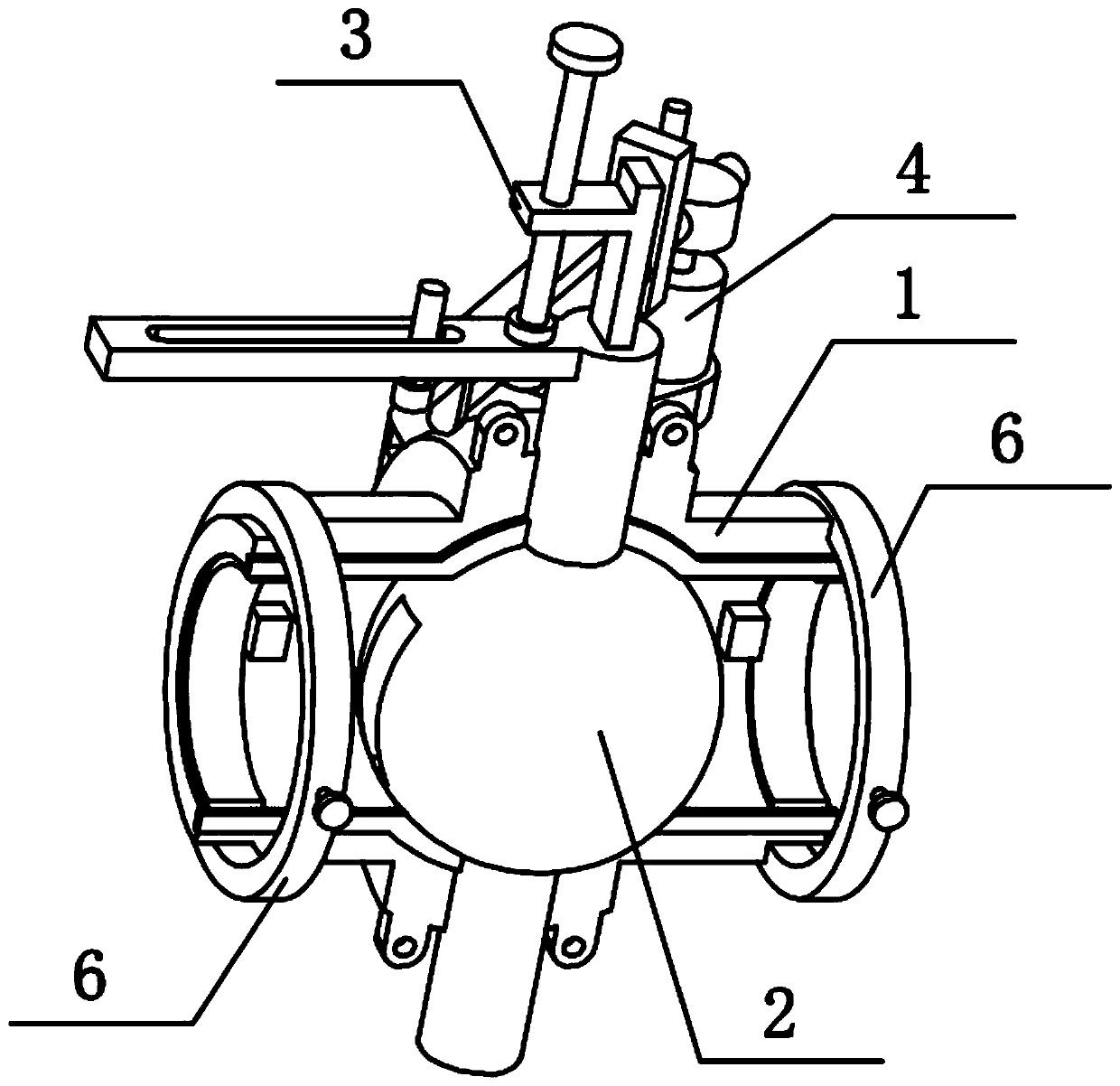
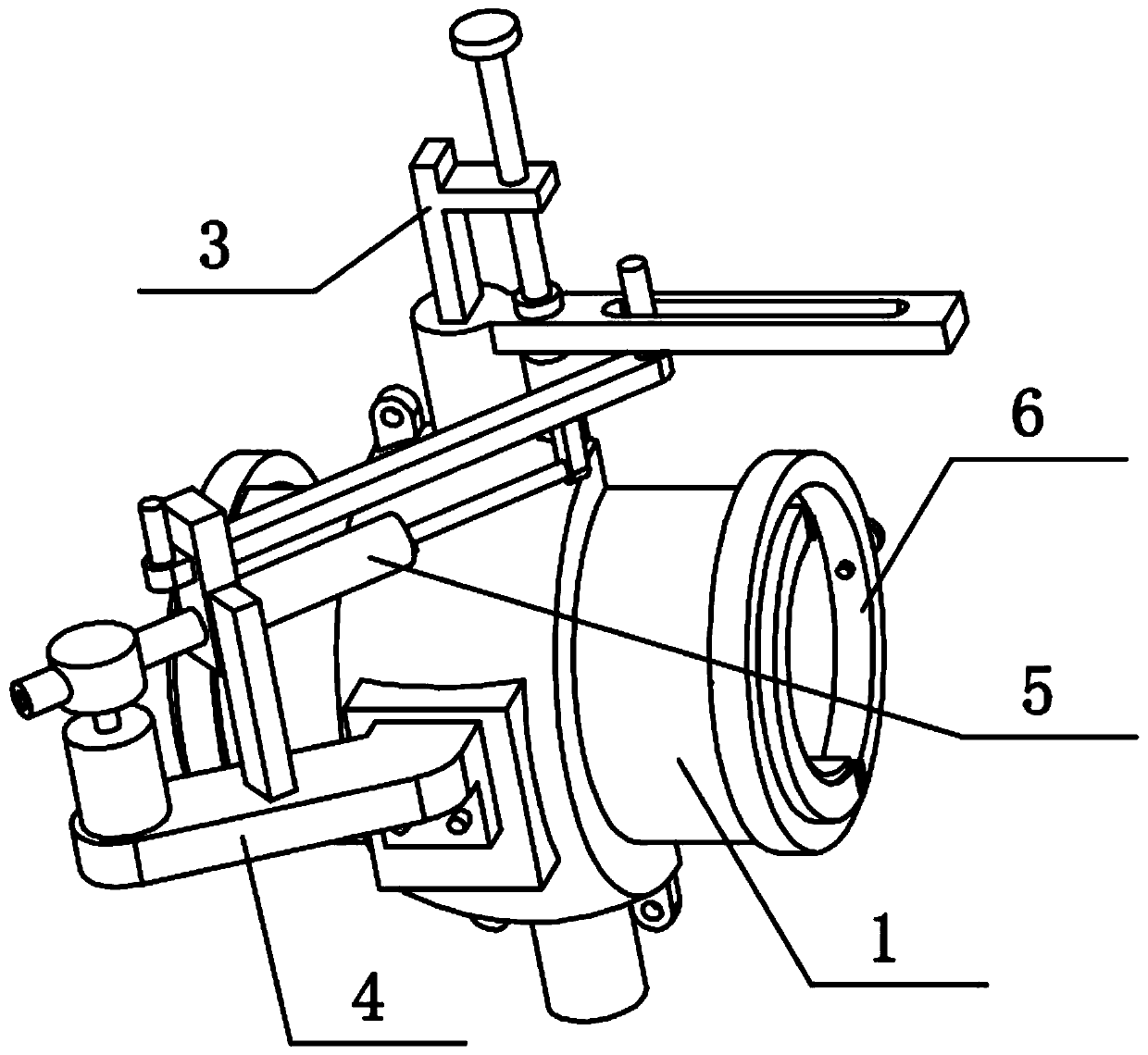
[0031] Combine below Figure 1-12 To illustrate this embodiment, the present invention relates to a ball valve, more specifically a pneumatic all-inclusive ball valve, including a housing 1, a rotating ball 2, a gate assembly 3, a pneumatic assembly 4, a telescopic assembly 5 and a ferrule 6. The invention can drive the rotating ball 2 to rotate through the pneumatic assembly 4, thereby controlling the opening and closing of the valve, and the gate assembly 3 can manually adjust the flow rate of the valve again, and the flow adjustment accuracy is high; when the inside of the valve needs to be repaired, the two shells 1 Easy to separate for easy repair of valve interior.

[0032] There are two shells 1 front and back, the two shells 1 are buckled and fixed together, the gate assembly 3 is rotatably connected between the two shells 1, the gate assembly 3 is arranged on the upper end of the rotating ball 2, and the pneumatic assembly 4 is fixed Connected to one of the shells 1,...

specific Embodiment approach 2

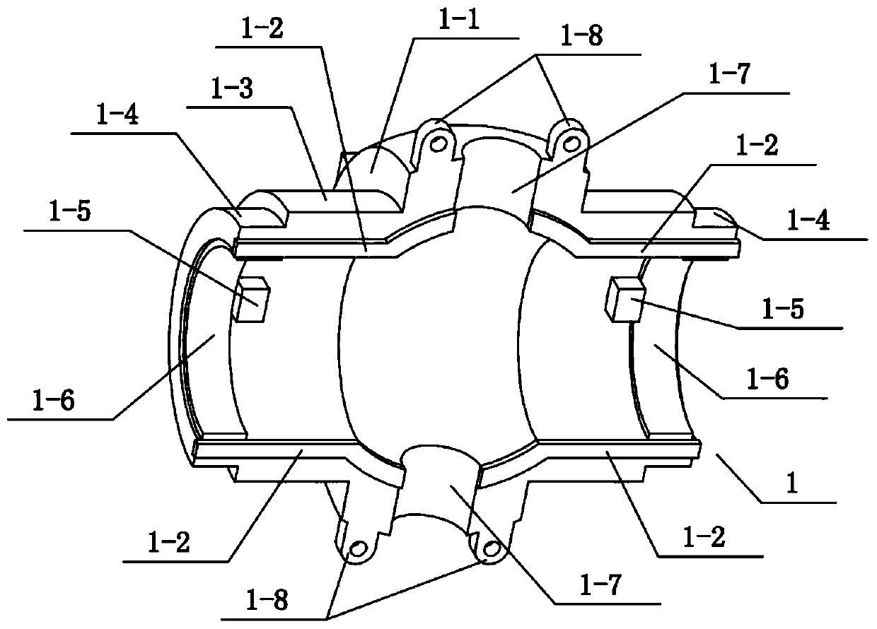
[0034] Combine below Figure 1-12Describe this embodiment, this embodiment will further explain Embodiment 1, the housing 1 includes a spherical shell 1-1, a sealing strip 1-2, a semicircular pipe 1-3, an annular groove 1-4, and a limiting post 1- 5. Internal thread 1-6, shaft hole 1-7, jack seat 1-8 and square seat 1-9, the left and right ends of spherical shell 1-1 are fixedly connected with semicircular pipe 1-3, two semicircular pipes The upper and lower ends of 1-3 are bonded with sealing strips 1-2, the upper and lower ends of spherical shell 1-1 are fixedly connected with two jack seats 1-8, and the upper and lower ends of spherical shell 1-1 are A shaft hole 1-7 is provided, a square seat 1-9 is provided on the outside of the spherical shell 1-1, an annular groove 1-4 is provided on the outside of the two semicircular tubes 1-3, and an annular groove 1-4 is provided on the inside of the two semicircular tubes 1-3. Both are provided with internal threads 1-6, and the i...

specific Embodiment approach 3

[0036] Combine below Figure 1-12 Describe this embodiment, this embodiment will further explain the second embodiment, the rotating ball 2 includes a round ball 2-1, an upper rotating shaft 2-2, a gate chute 2-3, a sliding orifice plate 2-4, a sliding Hole 2-5, water channel 2-6 and lower rotating shaft 2-7, ball 2-1 is provided with water channel 2-6, water channel 2-6 runs through ball 2-1 left and right, and ball 2-1 The upper and lower ends are respectively fixedly connected with an upper rotating shaft 2-2 and a lower rotating shaft 2-7, the ball 2-1 is rotatably connected between the two spherical shells 1-1, and the upper rotating shaft 2-2 is rotatably connected to the two upper rotating shafts Between the holes 1-7, the lower rotating shaft 2-7 is rotatably connected between the two rotating shaft holes 1-7 at the lower end, and the upper rotating shaft 2-2 is provided with a ram chute 2-3, and the ram chute 2-3 It communicates with the water channel 2-6, and the up...


PUM


Abstract

The invention relates to a ball valve, in particular to a pneumatic whole-packaging ball valve which comprises shells arranged in the front and back, a rotation ball, a gate component, a pneumatic component, a telescopic component and two ferrules arranged on the left and right respectively. For the pneumatic whole-packaging ball valve provided by the invention, the rotation ball is driven by thepneumatic component to rotate, so that opening and closing of a valve is controlled; in addition, the gate component can be used for manually regulating the flow rate of the valve again, and the regulation accuracy is relatively high; and when the interior of the valve is repaired, the two shells are convenient to separate, so that interior of the valve is convenient to repair. The two shells arebuckled and fixed together, the gate component is rotationally connected between the two shells, the gate component is arranged at the upper end of the rotation ball, the pneumatic component is fixedly connected to one shell and is in sliding connection with the rotation ball, the telescopic component is arranged on the pneumatic component, and the two ferrules are both connected between the two shells in a sleeving manner.

Description

technical field [0001] The invention relates to a ball valve, in particular to a pneumatic all-inclusive ball valve. Background technique [0002] The application number is CN201820172373.0 for a pneumatic ball valve. This utility model discloses a pneumatic ball valve, which includes a pneumatic ball valve body. One end of the pneumatic ball valve body is provided with a feed port, and the other end of the pneumatic ball valve body is provided with a connecting valve. One end of the connecting valve pipe is provided with a discharge port, and a fixing bolt is arranged between the body of the pneumatic ball valve and the connecting valve pipe. Both the body of the pneumatic ball valve and the connecting valve pipe are provided with fixing holes. The pneumatic ball valve There is a ball valve compartment inside the body. The utility model is provided with a sealing ring, a sealing pipe and a thrust plate, and the sealing ring can be used for sealing and anti-seepage between ...

Claims


Application Information

Patent Timeline
Patent Type & Authority Patents(China)
IPC IPC(8): F16K5/06F16K5/08F16K31/122
CPCF16K5/0663F16K5/08F16K31/122
Inventor 张叶华
Owner 拓姆菲阀门科技(安徽)有限公司
Why Eureka
Try Eureka