Dual-channel condenser with heat recovery and condensing temperature control structure

A technology to control the structure and condensation temperature, which is applied in the direction of evaporator/condenser, refrigerator, refrigeration components, etc., can solve the problems of low operating efficiency, affecting efficiency, and many equipment components, and achieve the effect of high operating efficiency and simple structure

Active Publication Date: 2012-03-28
CLIMAVENETA CHATUNION REFRIGERATION EQUIP SHANGHAI
View PDF8 Cites 7 Cited by
  • Summary
  • Abstract
  • Description
  • Claims
  • Application Information

AI Technical Summary

Problems solved by technology

This method has many equipment components, complicated production, low reliability, large resistance of the refrigerant circuit, high price, and low operating efficiency, especially when operating at part load.
Another way is that the heat recovery unit and the condenser are integrated in one shell, but each such heat exchanger can only correspond to one refrigeration circuit, that is, one compressor system corresponds to one heat exchanger, and for a unit with multiple compressors , requires multiple such heat exchangers, the manufacture is complicated, and when some compressors are running and some compressors are not running, it will cause temperature imbalance between different circuits, heat exchange between refrigerant and circulating water Large temperature difference, high condensing pressure, reduced system efficiency
[0004] In addition, the current water-cooled heat recovery unit cannot accurately control the temperature of the condenser, and the condensing temperature is unstable, so the water temperature on the side of the heat recovery cycle cannot be accurately controlled, and the operating efficiency of the unit is low under partial load conditions.

Method used


Image

  • Dual-channel condenser with heat recovery and condensing temperature control structure
  • Dual-channel condenser with heat recovery and condensing temperature control structure

Examples


Embodiment Construction

[0014] The specific implementation manners of the present invention will be described in detail below in conjunction with the accompanying drawings of the embodiments.

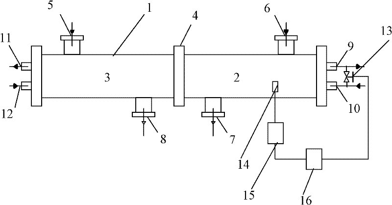
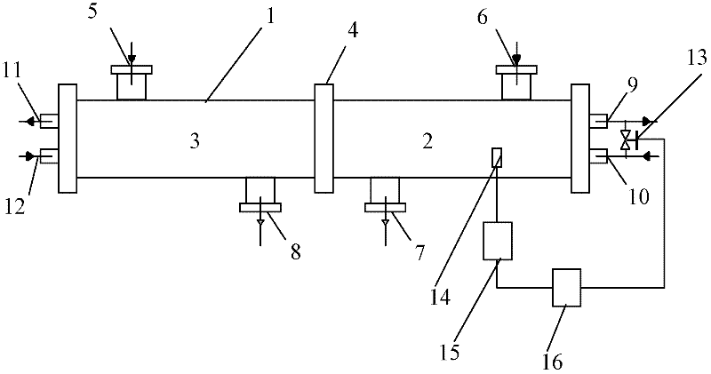
[0015] The double channel condenser with heat recovery and condensation temperature control structure of the present invention integrates the function of heat recovery device and the condensation function of ordinary condenser, and it is provided with three groups of inlets and outlets: refrigerant inlet and outlet, cooling water inlet and outlet and hot water circulation Import and export, see the specific structure figure 1 , the structure of this condenser is:

[0016] A tubular heat exchanger 1, with a metal baffle 4 in the middle, divides the tube body of the heat exchanger 1 into two parts, the first cavity 2 and the second cavity 3, and the metal baffle 4 is placed in the tube body Some have several through holes;

[0017] The first cavity 2 and the second cavity 3 are respectively provided with refri...


PUM


Abstract

The invention discloses a dual-channel condenser with a heat recovery and condensing temperature control structure, belonging to condensers, and solving the problems of unstable operation and condensing temperature of the existing equipment. The dual-channel condenser has a structure that the tube body of a tubular heat exchanger is divided into two cavities; a refrigerant inlet and a refrigerantoutlet are respectively formed on each cavity and connected with one compressor in a single cold type unit; a cooling water outlet and a cooling water inlet are formed on one end of one cavity and are communicated through a condensation heat exchange tube penetrating through the heat exchanger tube; a hot water circulation outlet and a hot water circulation inlet are formed on one end of the other cavity and are communicated through a heat recovery heat exchange tube penetrating through the heat exchanger tube; a by-pass electric valve is connected between the cooling water outlet and the cooling water inlet; and the valve control end of the by-pass electric valve is connected with a temperature controller communicated with the inside of the condensation heat exchange tube. Regardless of the operating mode of unit load in the condenser, heat exchange can be fully performed in the heat exchanger, the condensing temperature is stable, the operation efficiency of the unit is high, and simultaneously, one heat exchanger can correspond to two compressors, so that the unit structure is simpler.

Description

technical field [0001] The invention relates to a condenser, in particular to a double-channel condenser with heat recovery and condensation temperature control structures. Background technique [0002] The heat recovery of the chiller mainly refers to the recovery and utilization of the condensation heat. By recycling the condensation heat generated in the refrigeration cycle of the unit, hot water is produced to meet the various needs of users. Heat recovery mainly realizes the recovery of condensation heat through the heat exchange between the refrigerant and the circulating water through the heat recovery heat exchanger. The earliest condensation heat recovery technology is to exchange heat between the external series plate heat exchanger and circulating water of ordinary chillers to produce hot water. In this way, the water temperature is uncontrollable, the condensation pressure is unstable, and the system oil return is difficult during use. Many other problems have n...

Claims


Application Information

Patent Timeline
Patent Type & Authority Applications(China)
IPC IPC(8): F25B39/04
Inventor 陈睿
Owner CLIMAVENETA CHATUNION REFRIGERATION EQUIP SHANGHAI
Why Eureka
Try Eureka