
System and method to estimate compressional to shear velocity (vp/vs) ratio in a region remote from a borehole

A technology of compressional-to-short-wave velocity ratio and borehole, applied in seismology, seismology, instruments, etc. for logging records

Inactive Publication Date: 2012-03-28
CHEVROU USA INC +1
View PDF5 Cites 11 Cited by
  • Summary
  • Abstract
  • Description
  • Claims
  • Application Information

AI Technical Summary

Problems solved by technology

[0007] Although attempts have been made to characterize the nonlinear characteristics of formations in explored hydrocarbon regions from the borehole, each attempt has its own limitations

Method used


Image

  • System and method to estimate compressional to shear velocity (vp/vs) ratio in a region remote from a borehole
  • System and method to estimate compressional to shear velocity (vp/vs) ratio in a region remote from a borehole
  • System and method to estimate compressional to shear velocity (vp/vs) ratio in a region remote from a borehole

Examples


Embodiment Construction

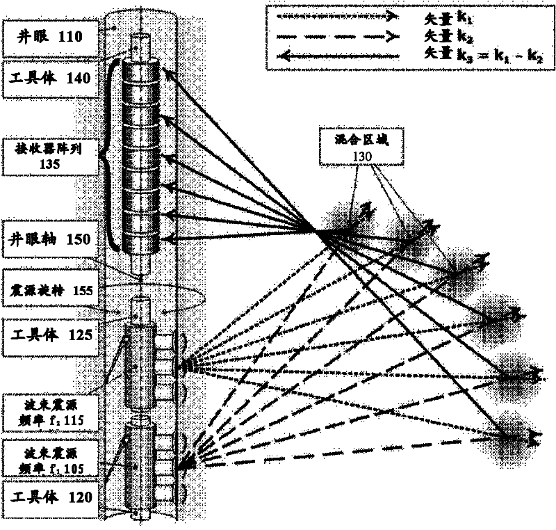
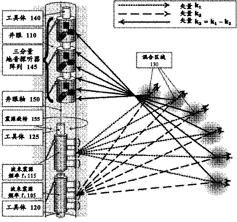
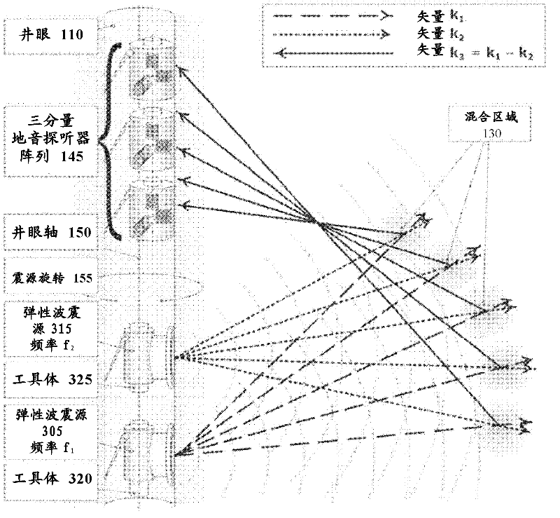
[0022] figure 1 One of several possible configurations for generating a three-dimensional image of the non-linear nature and the aspect wave velocity ratio in a region away from the borehole according to various aspects of the present disclosure is shown. The first seismic source 105 is placed in the borehole 110 at a first frequency f 1 Generate controllable primary beam acoustic energy. The second seismic source 115 is also placed in the borehole 110 at a second frequency f 2 Generate controllable primary beam acoustic energy. As a non-limiting example, both the first seismic source 105 and the second seismic source 115 may be a phased seismic source array and may be configured to generate either a longitudinal or a lateral controllable beam.

[0023] Such as figure 1 As shown, the first seismic source 105 is placed on the first tool body 120, and the second seismic source 115 is placed on the second tool body 125. However, the present disclosure is not limited to this, becaus...


PUM


Abstract

In some aspects of the disclosure, a method for creating three-dimensional images of non-linear properties and the compressional to shear velocity ratio in a region (130) remote from a borehole using a conveyed logging tool (140) is disclosed. In some aspects, the method includes arranging a first source (105) in the borehole (110) and generating a steered beam of elastic energy at a first frequency; arranging a second source (115) in the borehole (110) and generating a steerable beam of elastic energy at a second frequency, such that the steerable beam at the first frequency and the steerable beam at the second frequency intercept at a location (130) away from the borehole (110); receiving at the borehole (110) by a sensor (135) a third elastic wave, created by a three wave mixing process, with a frequency equal to a difference between the first and second frequencies and a direction of propagation towards the borehole (110).

Description

[0001] Cross references to related applications [0002] This application claims the benefit of U.S. Patent Application Serial No. 12 / 463,796 filed on May 11, 2010. This U.S. patent application claims priority for U.S. Provisional Patent Application No. 61 / 170,070 filed on April 16, 2009. The entire content is hereby quoted as a reference, according to 35U.SC§119(e). [0003] Government rights [0004] The present invention was carried out under the support of the government under the cooperative research and development agreement (CRADA) contract number DE-AC52-06NA25396 signed by the US Department of Energy. The government may have certain rights in this invention. Technical field [0005] Generally speaking, the present invention relates to seismic exploration of rock formations. More specifically, it relates to the use of a combination of seismic sources in a borehole configured to provide elastic energy to generate a three-dimensional image of the non-linear nature and the P / P w...

Claims


Application Information

Patent Timeline
IPC IPC(8): G01V1/46
CPCG01V1/006G01V2210/588G01V2210/127G01V2210/125G01V1/44
Inventor P·A·约翰逊武巩J·A·藤卡特R·古耶尔P-Y·勒巴斯K·T·尼赫伊D·P·施密特C·司科尔特
Owner CHEVROU USA INC
Learn More