
Method and apparatus for determining the nonlinear properties of devices and fibers

a nonlinear and optical technology, applied in the field of optical communication, can solve the problems of unwanted impairment, high cost, and complex generation of short optical pulses, and achieve the effects of reducing the number of optical pulses, and improving the accuracy of optical pulses

Active Publication Date: 2008-06-10
ALCATEL-LUCENT USA INC +1
View PDF6 Cites 2 Cited by
  • Summary
  • Abstract
  • Description
  • Claims
  • Application Information

AI Technical Summary

Benefits of technology

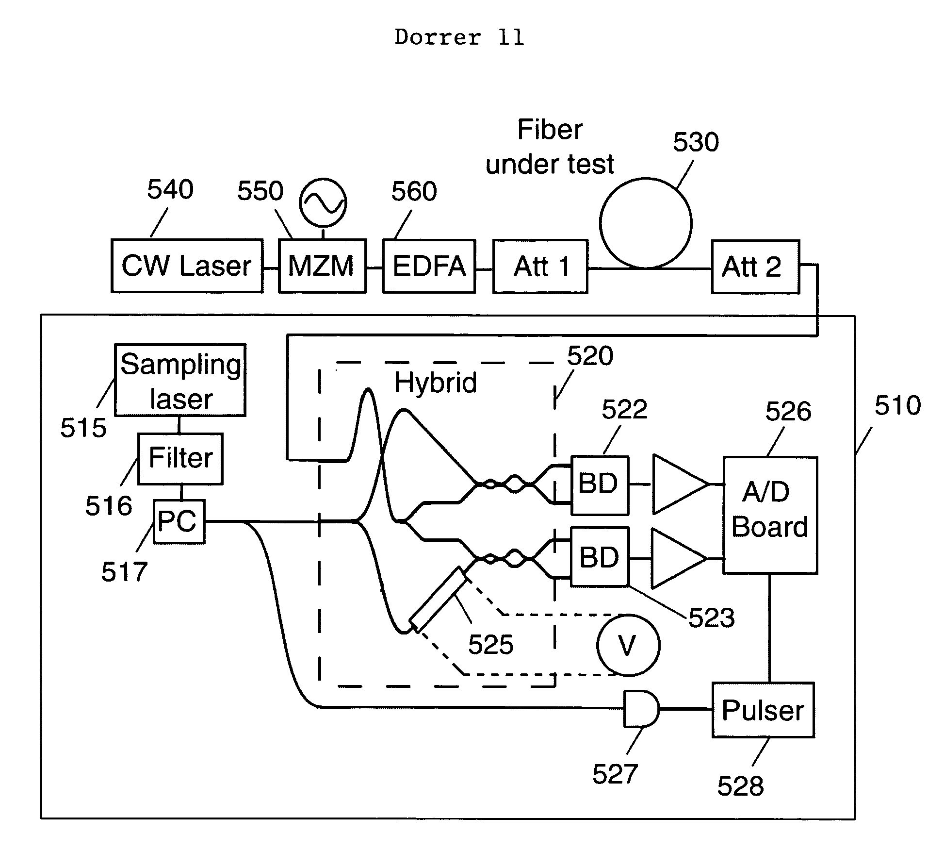
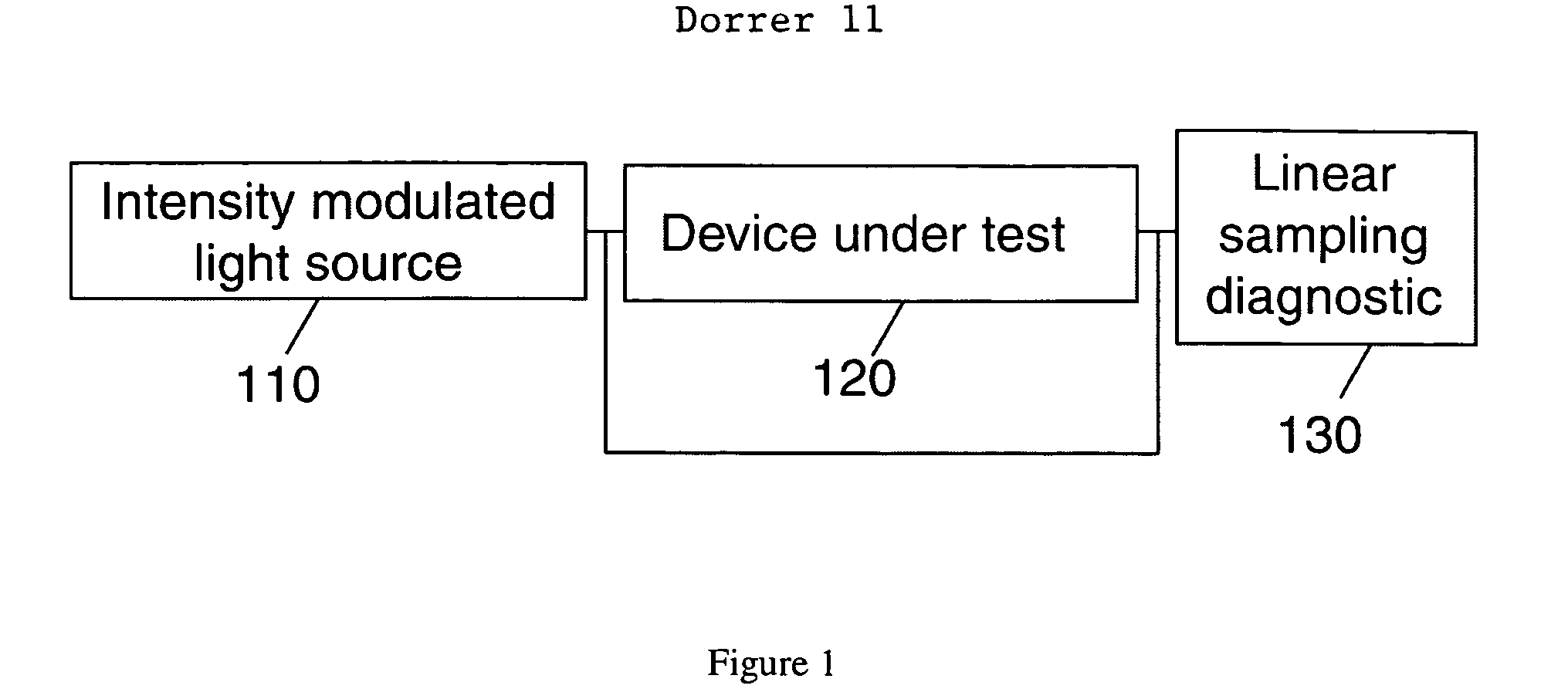
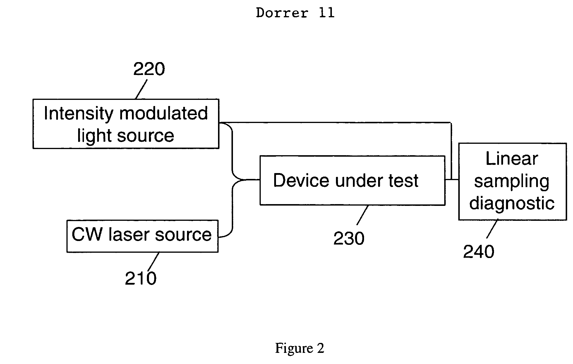
The present invention provides a method and apparatus for measuring the nonlinear properties of a device under test. This is done by measuring samples of the electric field of light before and after propagating the light through the device under test, and determining a nonlinear property of the device using the measured samples. The nonlinear property of the device can be determined by measuring the difference between the phase of samples measured before and after the light passes through the device, and using the intensity of the measured samples and the determined phase difference. Additionally, the nonlinear property of the device can be determined by measuring a plurality of samples of the electric field of light propagated through the device using different input powers, and using the proportionalities between the intensity and phase of the samples to determine a nonlinear parameter of the device.

Problems solved by technology

Nonlinear effects that cause unwanted impairments may occur during the propagation of light pulses in fibers and other optical devices.
For example, self phase modulation (SPM) and cross-phase modulation (XPM) are known to be limiting factors in long-haul optical networks.
A limitation of this technique is that the generation of short optical pulses can be complex and costly.
Furthermore, pulse characterization is usually devoted to pulses shorter than 100 ps, and these pulses can be modified by chromatic dispersion and polarization-mode dispersion during propagation in the device under test, thereby complicating any analysis of the results.
A limiting factor of this technique is that since the wavelengths of the two lasers must be very close to avoid the effects of chromatic dispersion and polarization-mode dispersion, the use of a costly high-resolution optical spectrum analyzer is typically required.
Since the determination of the nonlinear properties of the medium is indirect, it can be subject to errors that are difficult to track.

Method used


Image

  • Method and apparatus for determining the nonlinear properties of devices and fibers
  • Method and apparatus for determining the nonlinear properties of devices and fibers
  • Method and apparatus for determining the nonlinear properties of devices and fibers

Examples


Embodiment Construction

[0021]Methods and apparatus for measuring the nonlinear properties of a device are described. The nonlinear properties of a device (or fiber) under test are obtained by comparison of the phase and intensity of samples of the electric field of light measured before and / or after propagation through the device under test.

[0022]Although the present invention will be discussed in the context of a diagnostic system for use in the optical communication environment, those skilled in the art will appreciate that the present invention may be advantageously implemented in substantially any application where it is desirable to characterize nonlinear effects and / or to determine the nonlinear properties of a medium.

[0023]In accordance with aspects of the invention samples of the electric field (e.g. the intensity and phase) of light propagated through a fiber or other device under test can be measured using, for example, linear optical sampling.

[0024]In one preferred embodiment of the present inv...


PUM


Abstract

A method and apparatus are provided for measuring samples of the electric field of light propagated through a device under test and determining a nonlinear property of the device, such as self-phase modulation or cross phase modulation, using the measured samples.

Description

BACKGROUND OF THE INVENTION[0001]The present invention generally relates to the field of optical communications and more particularly to methods and apparatus for determining nonlinear properties of optical devices and fibers.[0002]Nonlinear effects that cause unwanted impairments may occur during the propagation of light pulses in fibers and other optical devices. For example, self phase modulation (SPM) and cross-phase modulation (XPM) are known to be limiting factors in long-haul optical networks. SPM and XPM effects correspond to an induced temporal phase that is related to the temporal intensity of the pulses themselves (in the case of SPM) or to the temporal intensity of another optical source or a combination of optical sources (in the case of XPM). The coupling between the intensity and phase depends upon the medium, the characteristics of the interacting waves (for example the state of polarization and wavelength) and the nonlinear interaction. For example, in an optical fi...

Claims


Application Information

Patent Timeline
Patent Type & Authority Patents(United States)
IPC IPC(8): G01B9/02
CPCG01M11/333
Inventor DORRER, CHRISTOPHE J.
Owner ALCATEL-LUCENT USA INC
Learn More