Methods and apparatus to couple an electro-pneumatic controller to a position transmitter in a process control system

A pneumatic controller, process control technology, applied in the field of controllers

Inactive Publication Date: 2012-03-28
FISHER CONTROLS INT LLC
View PDF3 Cites 2 Cited by
  • Summary
  • Abstract
  • Description
  • Claims
  • Application Information

AI Technical Summary

Problems solved by technology

These electronic controls cause proce

Method used


Image

  • Methods and apparatus to couple an electro-pneumatic controller to a position transmitter in a process control system
  • Methods and apparatus to couple an electro-pneumatic controller to a position transmitter in a process control system
  • Methods and apparatus to couple an electro-pneumatic controller to a position transmitter in a process control system

Examples


Embodiment Construction

[0010] Although the following describes exemplary methods and apparatus that include, among other components, software and / or firmware executing on hardware, it should be noted that such systems are exemplary only and should not be considered as restrictive. For example, it is contemplated that any or all of these hardware, software, and firmware components may be implemented entirely as hardware, entirely as software, or as any combination of hardware and software. Therefore, while the exemplary methods and apparatus are described below, the examples provided are not the only way to practice the method and apparatus.

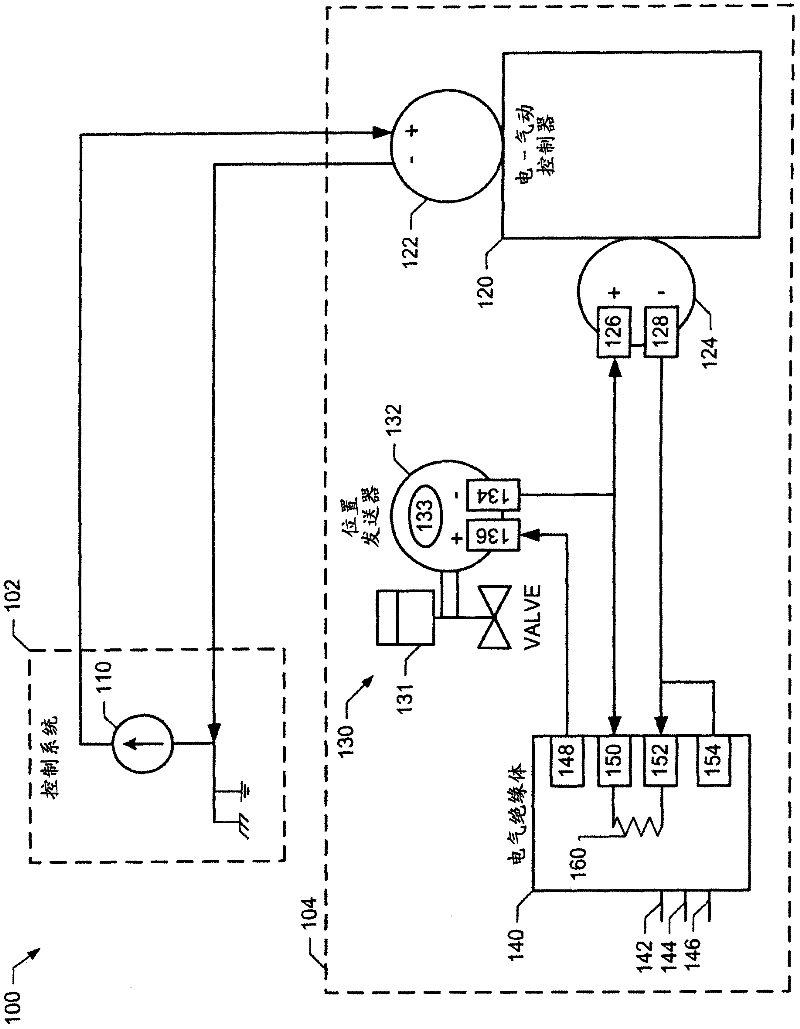
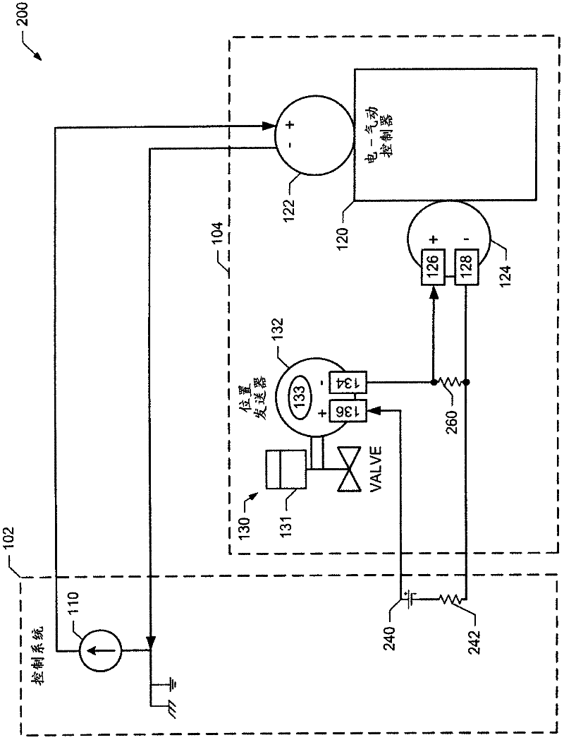
[0011] Typically, in process control systems, electro-pneumatic controllers are directly coupled to control devices, (eg, control valves, pumps, dampers, etc.). A position sensor coupled to the control device detects movement of an actuator coupled to the control device. The position sensor may send a feedback signal comprising a current having a magnitude co...


PUM


Abstract

Example methods and apparatus to couple an electro-pneumatic controller to a position transmitter in a process control system are disclosed. A disclosed example apparatus includes a position transmitter having a first connection and having a second connection coupled to a power source, an electro-pneumatic controller including at least a first connection coupled to the first connection of the position transmitter, and a resistor coupled between the first connection and a second connection of the electro-pneumatic controller.

Description

technical field [0001] The present disclosure relates generally to controllers and, more particularly, to methods and apparatus for coupling electro-pneumatic controllers to position transmitters in process control systems. Background technique [0002] Electronic control devices (eg, electro-pneumatic controllers, programmable controllers, analog control circuits, etc.) are typically used to control process control devices (eg, control valves, pumps, dampers, etc.). These electronic control devices cause specific operation of the process control device. For safety, cost-efficiency, and reliability purposes, many well-known diaphragm or piston-type pneumatic actuators are used to drive process control devices and are typically coupled to the overall process control system through an electro-pneumatic controller. Electro-pneumatic controllers are typically configured to receive one or more control signals and convert these control signals into pressures that are provided to ...

Claims


Application Information

Patent Timeline
IPC IPC(8): G05B19/44G08C19/02
CPCG05B19/44G05B2219/34191G05B2219/41315
Inventor S·G·塞伯格S·W·哈根L·D·米勒
Owner FISHER CONTROLS INT LLC
Why Eureka
Try Eureka