Pin-type gripper device

A fixture device and nail-type technology, which is applied to workpiece clamping devices, manufacturing tools, etc., can solve the problems of large device scale, increased probability of failure and error, high cost and time, etc., and achieves simple structure and control. economic effect

Active Publication Date: 2012-04-04
KOREA PNEUMATIC SYST CO LTD
View PDF6 Cites 8 Cited by
  • Summary
  • Abstract
  • Description
  • Claims
  • Application Information

AI Technical Summary

Problems solved by technology

[0006] First, the structure of the device becomes more complex, and at the same time, the scale of the entire device including the outer cover becomes larger;
[0007] Second, in order to be able to control two gas cylinders at the same time, a special and specific design is required, and at the same time, the probability of failure and error will increase;
[0008] Third, in the end, more money and time must be invested in the production of the installation and its use

Method used


Image

  • Pin-type gripper device
  • Pin-type gripper device
  • Pin-type gripper device

Examples


Embodiment Construction

[0034] The features and effects of the present invention described or not described above will be further illustrated by the embodiments described below with reference to the accompanying drawings. figure 2 In the subsequent drawings, the nail clamp device of the present invention is indicated by the symbol 100.

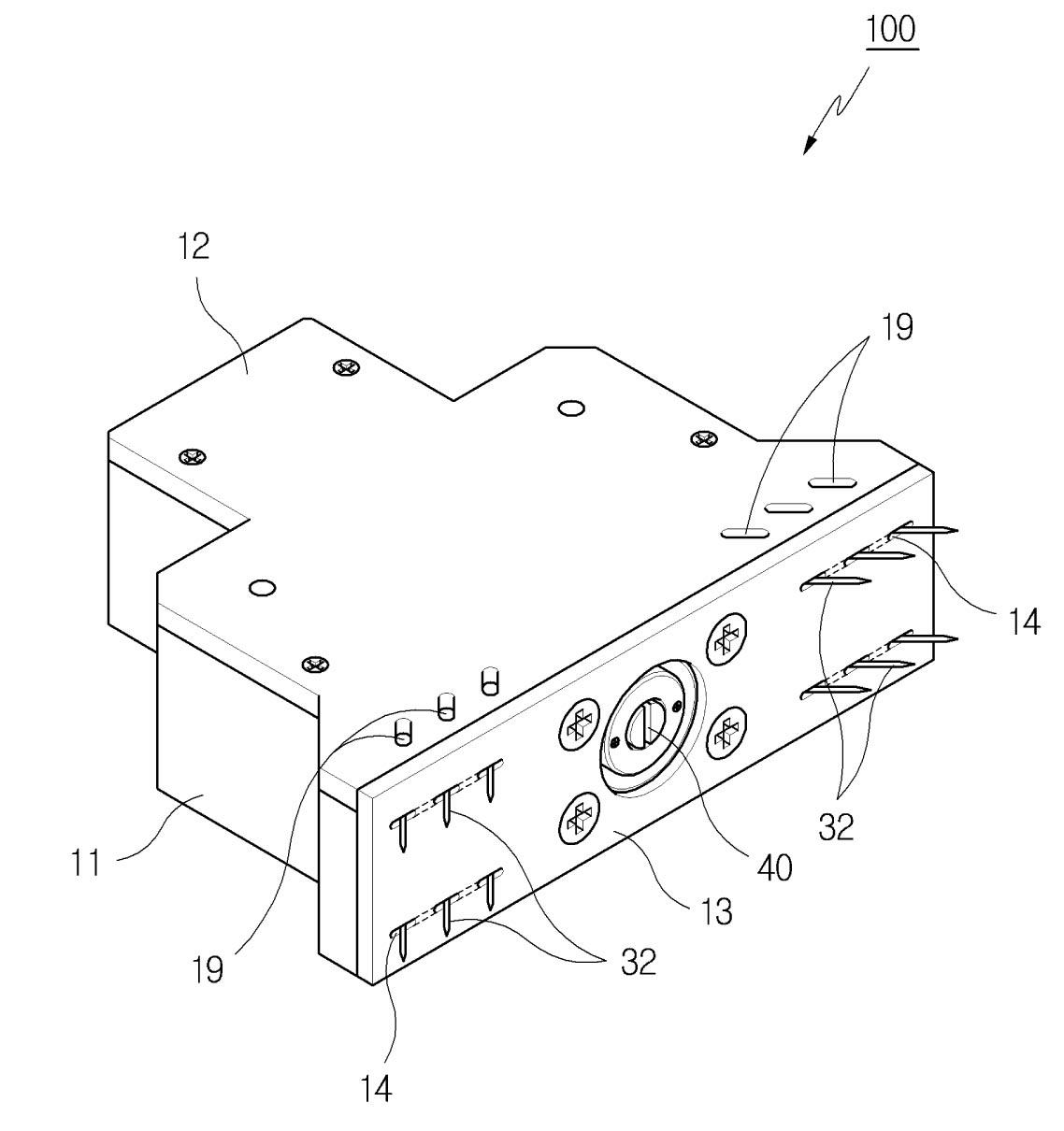
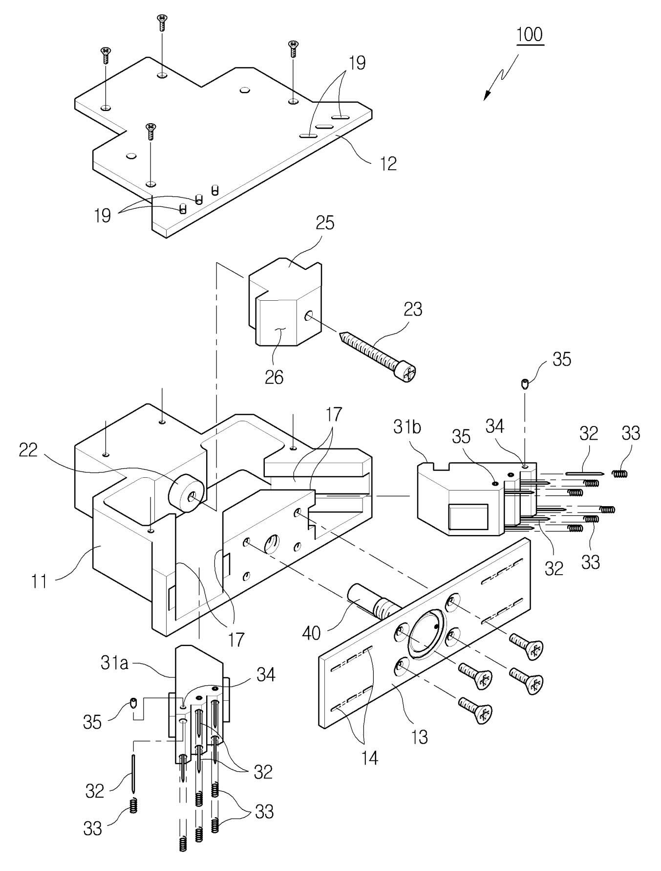
[0035] Reference Figure 2 to Figure 4 It can be seen that the nail clamp device (100) of the present invention includes an outer cover (10), an air cylinder unit (20) organically arranged in the outer cover (10), and a running part (30). The number of the pump unit (10) provided in the device (100) of the present invention is only one.

[0036] The body (11) of the outer cover (10) is provided with an internal space that can ensure the most suitable installation and movement of the air cylinder unit (20) and the operating part (30). The body (11) is closed by a cover plate (12) and a bottom plate (13). The bottom plate (13) is the bottom surface of the outer cover (10)...


PUM


Abstract

The invention provides a pin-type gripper device for clamping and transporting soft objects. The device is composed of the following parts: a central cylinder unit comprising a piston with a conical body at the end; and a pair of slide components which are obliquely arranged along the left and right sides of the conical body in a face-to-face manner and are spread like a skirt. A pin for insertion into an object is mounted to the ends of the slide components. The device of the invention is capable of controlling the two slide components simultaneously using only one cylinder unit. Therefore, compared with a conventional device needing two cylinders and with complex design, the device of the invention is simpler and more economical in terms of structure and control.

Description

technical field [0001] The present invention relates to a clamp device, and specifically relates to a so-called nail type clamp device which uses nails to clamp an object. Background technique [0002] The so-called gripper device refers to a device that clamps an object by applying physical force or pressure, and it is mainly used in a transfer system. Especially for objects made of soft materials such as fabrics or porous materials, rubber, etc., a so-called "nail type" clamp device is generally used. [0003] refer to figure 1 It can be seen that the nail clamp device (1) in the prior art includes two gas cylinders (3a, 3b) arranged obliquely downward in the outer cover (2) along mutually intersecting directions. A plurality of nails (6a, 6b) are respectively set at the end of the piston rod (4a, 4b) of each air cylinder (3a, 3b) through the medium of the fixing assembly (5a, 5b). Here, the nails (6a, 6b) on both sides 6b) In fact, it is in a crossing state at the oppo...

Claims


Application Information

Patent Timeline
Patent Type & Authority Applications(China)
IPC IPC(8): B25B11/00
Inventor 赵镐英
Owner KOREA PNEUMATIC SYST CO LTD
Why Eureka
Try Eureka