
Method for obtaining mechanical joint stiffness

A joint and stiffness technology, applied in the field of obtaining the stiffness of mechanical joints, can solve problems such as inaccurate stiffness performance analysis

Inactive Publication Date: 2012-04-04
XIAN UNIV OF TECH
View PDF2 Cites 11 Cited by
  • Summary
  • Abstract
  • Description
  • Claims
  • Application Information

AI Technical Summary

Problems solved by technology

[0005] The purpose of the present invention is to provide a method for obtaining the stiffness of the mechanical joint, which solves the problem of inaccurate analysis of the stiffness performance of the joint of the whole machine composed of multiple parts in the prior art

Method used


Image

  • Method for obtaining mechanical joint stiffness
  • Method for obtaining mechanical joint stiffness
  • Method for obtaining mechanical joint stiffness

Examples


Embodiment

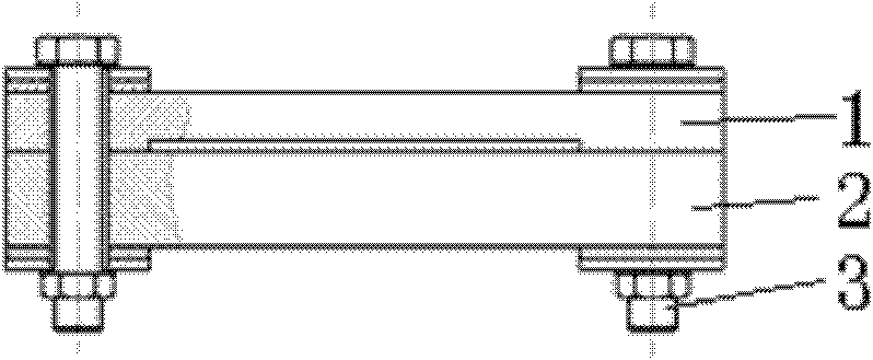
[0042] figure 1 It is a schematic diagram of the structure of the experimental object, in which the size of the upper plate 1 is 300mm×400mm×25mm, and the density of the upper plate 1 is 8100Kg / m 3 , the modulus of elasticity is 2.07×10 11 Pa, Poisson's ratio is 0.28. The size of the lower plate 2 is 300mm×400mm×40mm, and the density of the lower plate 2 is 6980Kg / m 3 , the modulus of elasticity is 1.01×10 11Pa, Poisson's ratio is 0.245. The contact force between the two plates is applied by four identical bolts 3 . Rubber, spacers and thrust bearings are padded between the bolt 3 and the two plates. The contact stiffness between the two plates is much larger than that of the rubber, so that the joint of the guide rail can be isolated. The data measured in the experiment are only for the joint surface where the upper and lower plates are pressed against each other. The average surface pressure loaded between the upper and lower plates is 0.06 MPa. The experimental device...


PUM


Abstract

The invention discloses a method for obtaining mechanical joint stiffness. The method is implemented according to the following steps: firstly, a pulse excitation method is adopted so as to obtain resonance frequency of an actual structure; secondly, an upper contact layer and a lower contact layer of a joint are regarded as a virtual material so as to build a finite element analytical model of an overall structure comprising the joint; and thirdly, a group of initial values of normal stiffness Kn and tangent stiffness Kt is firstly preset, and the preset values of the normal stiffness Kn and the tangent stiffness Kt are revised after the natural frequency which is obtained through computing and the resonance frequency which is obtained through experiment are compared with each other so as to ensure that the natural frequency which is obtained through computing continuously approaches the resonance frequency which is obtained through experiment until the natural frequency which is obtained through computing is approximate enough with the resonance frequency which is obtained through experiment, then last preset group of values of the normal stiffness Kn and the tangent stiffness Kt is the joint stiffness final fixed value which is obtained through adopting the method. In the method adopted by the invention, the iterative method is adopted so as to continuously adjust the design variable, and the finally obtained design variable is the joint stiffness data.

Description

technical field [0001] The invention belongs to the technical field of mechanical detection and relates to a method for obtaining the rigidity of a mechanical joint. Background technique [0002] The junction refers to the contact surfaces of two machine parts and the surrounding auxiliary structures. The main purpose of the junction research is to explore the change law of contact stiffness and damping, obtain contact stiffness and damping data, and realize the performance analysis and prediction of the whole machine. [0003] Joints have a significant impact on the static and dynamic characteristics of the machine tool. According to statistics, 30%-50% of the static stiffness of the machine tool comes from the stiffness of the joint, more than 60% of the dynamic flexibility of the machine tool comes from the joint, and more than 90% of the damping value of the machine tool comes from the joint. The design of modern machine tools, especially the design of high-end CNC mach...

Claims


Application Information

Patent Timeline
IPC IPC(8): G01M7/02
Inventor 王世军赵金娟马敬志郭璞
Owner XIAN UNIV OF TECH
Learn More