
Battery module

A technology for battery modules and single cells, applied to secondary batteries, battery pack components, circuits, etc., can solve the problems of bulging deformation, shortened life, performance degradation, etc., and achieve the effect of suppressing bulging deformation and preventing deterioration

Active Publication Date: 2012-04-04
HONDA MOTOR CO LTD
View PDF5 Cites 21 Cited by
  • Summary
  • Abstract
  • Description
  • Claims
  • Application Information

AI Technical Summary

Problems solved by technology

[0004] However, in the unit cells of the above-mentioned battery assembly, due to overcharging→decomposition of the electrolyte→increase in the internal pressure of the battery, the central part of the relatively weak unit cell is bulged and deformed, resulting in degradation of its performance and life expectancy. Issues with undesirable situations such as shortening

Method used


Image

  • Battery module
  • Battery module
  • Battery module

Examples


Embodiment Construction

[0040] Hereinafter, embodiments of the invention will be specifically described based on examples of the invention illustrated in the drawings.

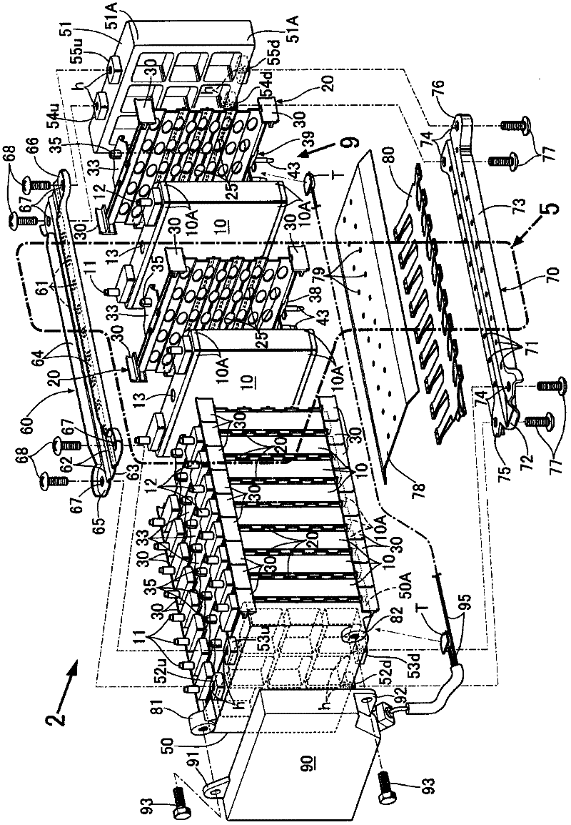
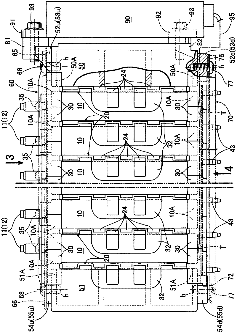
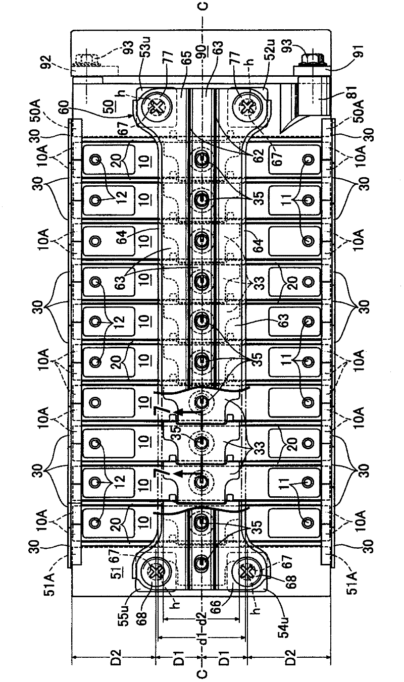
[0041] like figure 1 As shown, the battery module of the present invention includes a plurality of square cells 10 arranged side by side at intervals, a plurality of brackets 20 arranged between the cells 10 and outside the outermost cell 10 , A square-shaped end plate 50 disposed on the outside of one of the outermost brackets 20, and a square-shaped end plate (base end plate) 51 disposed on the outside of the other outermost bracket 20 are connected to each other. A plurality of single cells 10 and holders 20 stacked in close contact are clamped by a pair of end plates 50 and 51 on one side and the other side, and the end plates 50 and 51 pass through the upper connection frame 60 and the lower connection frame as connection members. 70 and united into one body. Furthermore, a voltage sensor assembly 90 (voltage sensor) is couple...


PUM


Abstract

The present invention provides a battery module. The battery module is formed by laminating a plurality of rectangular cells (10) and holders (20) and connecting them with the end plates at the outer side of the parallel direction thereof through jointing members to inhibit the projection deformation of a plurality of cells (10). The joining members (60, 70) join the first and second end plates (50, 51) to fasten the plurality of rectangular cells and the holders to be a single unit. Ends of the joining members are fastened to first securing parts (52u, 54u) and second securing parts (53u, 55u) on the first and second end plates. The first securing parts and the second securing parts are disposed at both ends of a center line (C-C) that penetrates through centers of the plurality of rectangular cells, the holders, and the first and second end plates. A distance between the center line and each of the first and second securing parts is smaller than a distance between each of the first and second securing parts and each of outermost surfaces of the first and second end plates.

Description

technical field [0001] The present invention relates to a battery module constituting a secondary battery mainly used as a power source for driving a motor of a hybrid vehicle or an electric vehicle. Background technique [0002] Conventionally, as such a battery module, there is known a battery assembly (battery module) including a plurality of parallel square unit cells 11 (cells), and partition walls for maintaining the intervals between the unit cells at a constant interval. , an end plate closely attached to the outer surface of the outermost unit cell 11 , and a connecting rod 30 integrating them (see Patent Document 1 described later). [0003] [Patent Document 1] Japanese Patent Laid-Open No. 2006-310309 [0004] However, in the unit cells of the above-mentioned battery assembly, due to overcharging→decomposition of the electrolyte→increase in the internal pressure of the battery, the central part of the unit cell with relatively weak strength is bulged and deformed...

Claims


Application Information

Patent Timeline
Patent Type & Authority Applications(China)
IPC IPC(8): H01M2/20H01M2/10H01M50/209H01M50/227H01M50/24H01M50/264
CPCY02E60/12H01M2/1229H01M2/1072H01M10/5055H01M2/1016H01M10/5032H01M10/647H01M10/6555Y02E60/10H01M50/325H01M50/209H01M50/24H01M50/264H01M50/227
Inventor 小栗浩辅夏梅征彦川田政夫
Owner HONDA MOTOR CO LTD
Learn More