Electric connecting terminal

A technology of electrical connection and electrical connection sheet, which is applied in the field of electrical connection terminals, can solve the problems of troublesome manufacturing and installation, waste of materials, and difficulty in ensuring the reliability of electrical connections, and achieve the effect of reducing the number of parts and ensuring reliability

Inactive Publication Date: 2012-04-04
CHANGSHU HONGLIN CONNECTING TECH
View PDF4 Cites 1 Cited by
  • Summary
  • Abstract
  • Description
  • Claims
  • Application Information

AI Technical Summary

Problems solved by technology

Although this method can achieve the purpose of making the bypass diode, the lead-out cables and the terminals for fixing the bus bar form an electrical circuit, there are at least the following problems: the one is that the number of electrical connection terminals is large, which not only brings troubles to manufacture and installation, Moreover, materials are wasted; second, it is difficult to ensure the reliability of electrical connections; third, the overall structure is loose and it is not conducive to reducing the volume of the solar photovoltaic cell box

Method used


Image

  • Electric connecting terminal
  • Electric connecting terminal
  • Electric connecting terminal

Examples


Embodiment 1

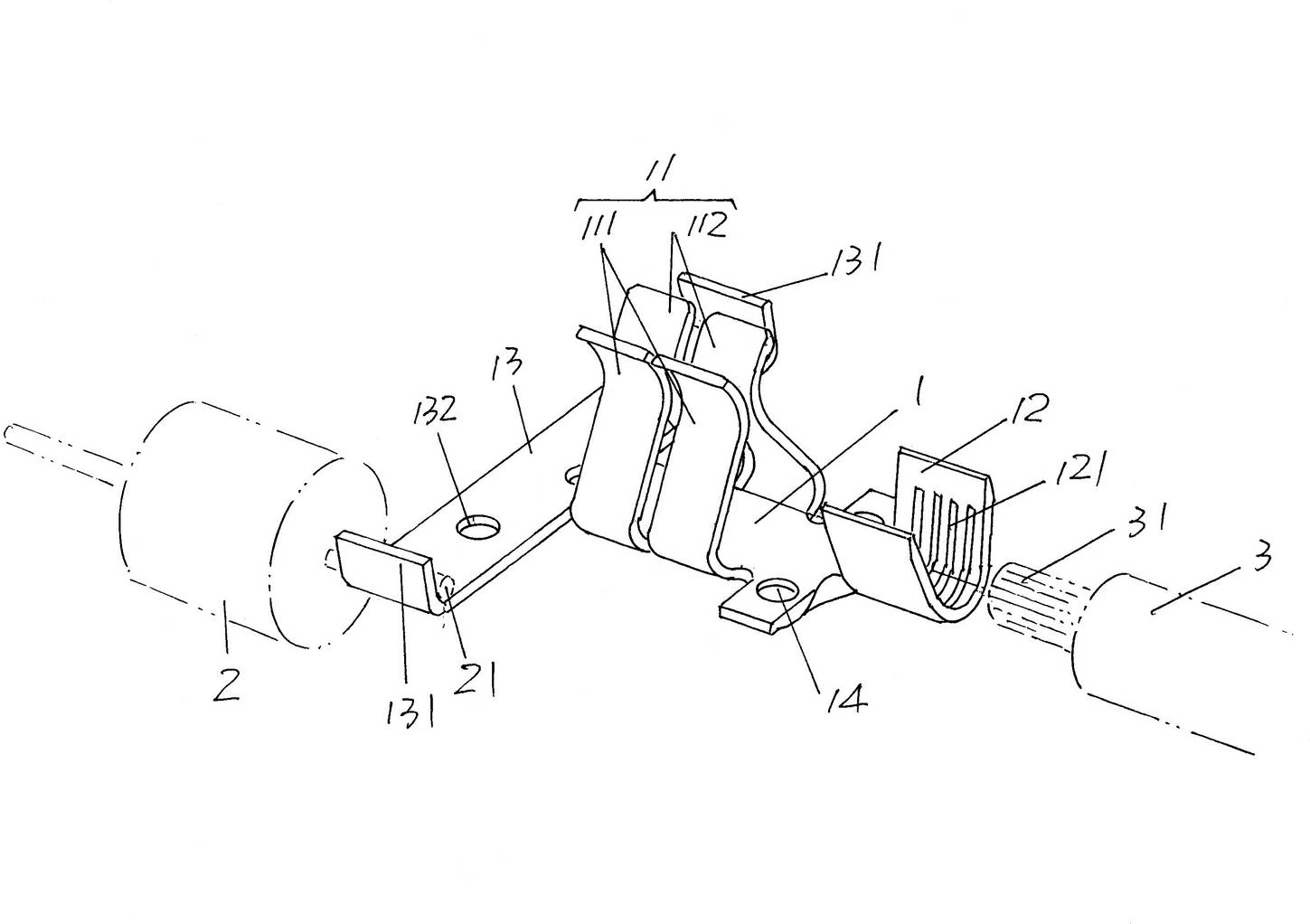
[0017] please see figure 1 , provides an electrical connector body 1 made of conductive material, that is, a metal material such as copper or iron, a pair of first latching members 11 are formed in the middle of the electrical connector body 1, and each first latching member 11 is It is composed of a first clip 111 and a second clip 112. The first and second clips 111, 112 are extended and formed on both sides of the electrical connector body 1 facing each other, and the first and second clips 111, 112 cooperate with each other. into a clip shape. At one end of the electrical connector body 1 ( figure 1 The shown right end) constitutes a second latching member 12 , the preferred but not absolutely limited shape of the second latching member 12 is U-shaped, and an engaging flange 121 is formed on the inner wall. At the other end of the electrical connector body 1 ( figure 1 The left end of the shown position state) constitutes a connecting foot 13 , a retaining foot 1...

Embodiment 2

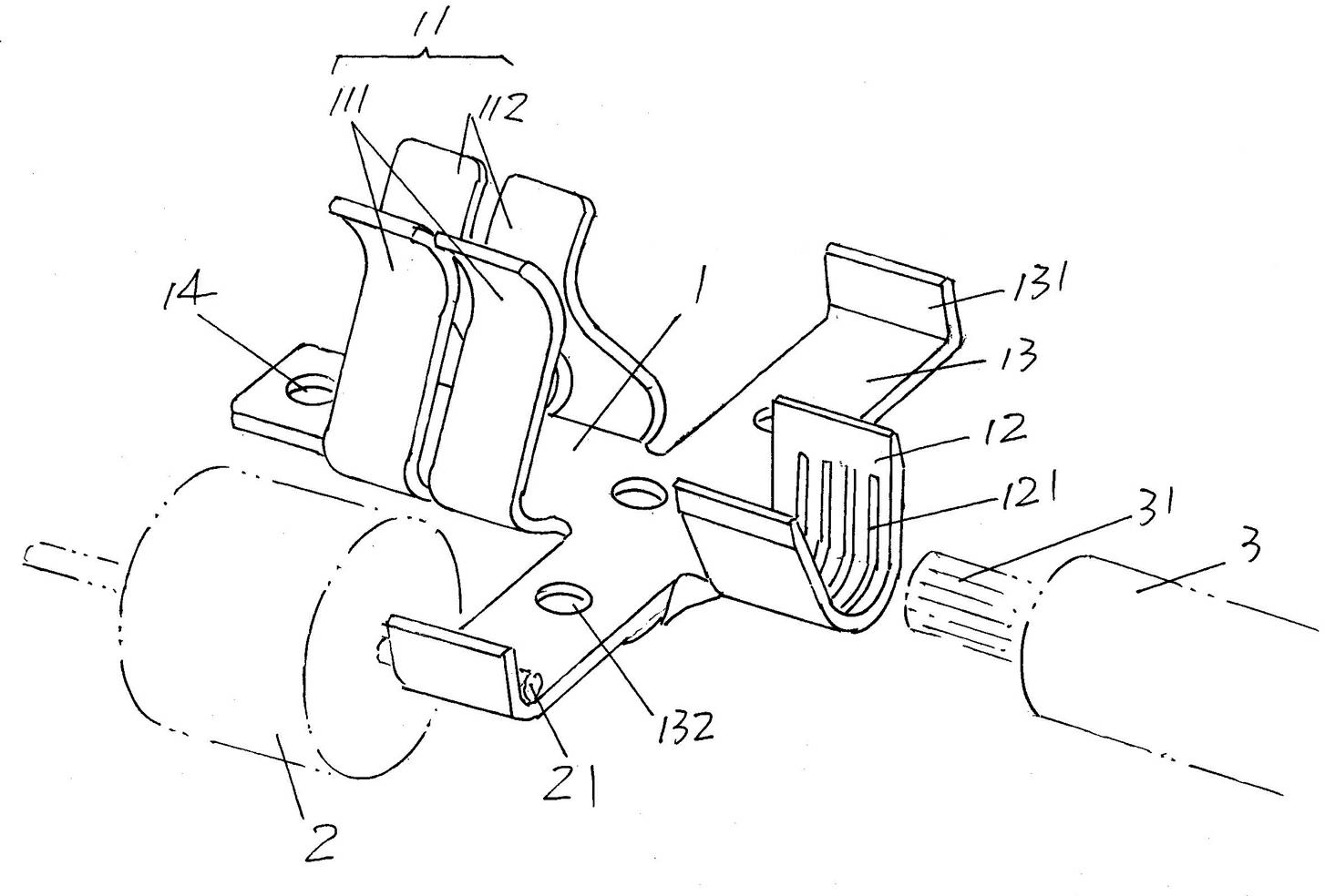
[0022] please see figure 2 , only the position of the connecting pin 13 on the electrical connector body 1 is changed to be located between the first locking member 11 and the second locking member 12, and the rest are the same as the description of the first embodiment.

Embodiment 3

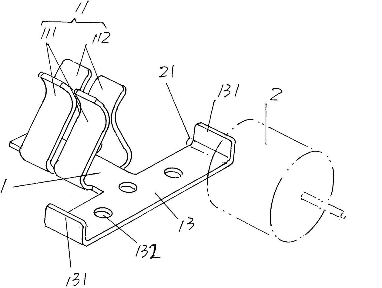
[0024] please see image 3 , compared to figure 1 and figure 2 In other words, the second latch 12 for the connection of the outgoing cable 3 is omitted, the image 3 The structure shown can be used not only in solar photovoltaic cell junction boxes, but also in other occasions, for example, for electrical circuit connections in electrical control boxes such as automation control equipment.


PUM


Abstract

The invention discloses an electric connecting terminal, which belongs to the technical field of electric connectors. The electric connecting terminal comprises an electric connecting sheet body. A first clamping part, a second clamping part and connecting pins are formed on the electric connecting sheet body integrally. The electric connecting terminal has the following advantages of: the first clamping part, the second clamping part and connecting pins are formed on the electric connecting sheet body integrally in the technical scheme, so the quantity of parts can be dramatically reduced compared with the prior art and the ideal integrated characteristic is represented. The first clamping part, the second clamping part and connecting pins are formed on the electric connecting sheet body integrally, so reliable electric connection can be guaranteed to present ideal using effect; the electric connecting terminal has high installing efficiency, and can not only reduce the installing intensity of labors but also save labor resources; and the electrical connecting terminal is simple in entire structure and convenient to reduce volume.

Description

technical field [0001] The invention belongs to the technical field of electrical connectors, and in particular relates to an electrical connection terminal, which is applied to the electrical connection of electronic and electrical products, automation control equipment, robots and even solar photovoltaic cell components . Background technique [0002] Electrical connection terminals are widely used as circuit transition parts between at least two electrical components and are not limited to the above-mentioned occasions, and the rationality of the electrical connection terminal structure is not only important for the connection reliability between electrical components but also for Ease of connection makes a difference. Taking the solar photovoltaic cell junction box as an example, the electrical connection terminals provided in the box must be connected to the bypass diode, the lead-out cable, and the bus bar of the solar photovoltaic cell. However, in the prior art, ...

Claims


Application Information

Patent Timeline
Patent Type & Authority Applications(China)
IPC IPC(8): H01R11/05
Inventor 王军华叶科华陆红雨
Owner CHANGSHU HONGLIN CONNECTING TECH
Why Eureka
Try Eureka