Floating connector component and floating connector thereof

A floating connector and connector technology, which is used in the installation of connecting parts, the parts of connecting devices, and the connection, etc., can solve the problem of aggravating the mutual wear of the guide column and the guide sleeve, reducing the guide positioning accuracy, and fixing the connector and the floating connector. Re-plug inconvenience and other problems, to achieve the effect of reducing the automatic offset and reducing the requirements of the matching accuracy

Inactive Publication Date: 2012-04-04
CHINA AVIATION OPTICAL-ELECTRICAL TECH CO LTD
View PDF9 Cites 13 Cited by
  • Summary
  • Abstract
  • Description
  • Claims
  • Application Information

AI Technical Summary

Problems solved by technology

However, since there is no holding structure on the guide column, that is, the guide column is freely floating and assembled on the installation panel through its floating section during work, so when the fixed connector and the floating connector are separated, the floating connector is in its position. Under the action of its own gravity, it is inevitable that the downward offset will occur until the maximum offset distance is reached. When plugging in again, it must be guided by the guide post and guide sleeve. This is the reconnection between the fixed connector and the floating connector. Plugging and unplugging brings inconvenience, and also intensifies the mutual wear between the guide column and the guide sleeve, reducing the positioning accuracy of the two guides

Method used


Image

  • Floating connector component and floating connector thereof
  • Floating connector component and floating connector thereof
  • Floating connector component and floating connector thereof

Examples


Embodiment Construction

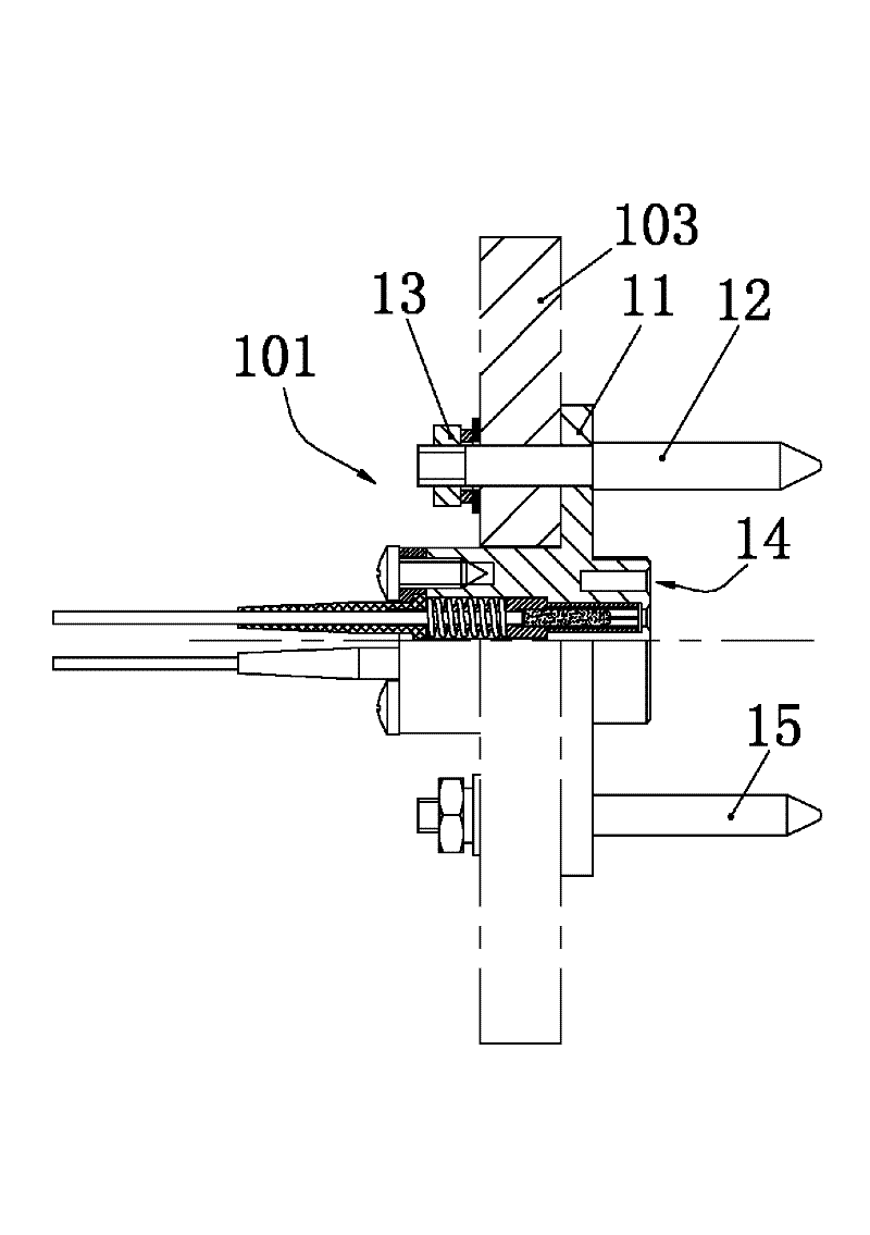
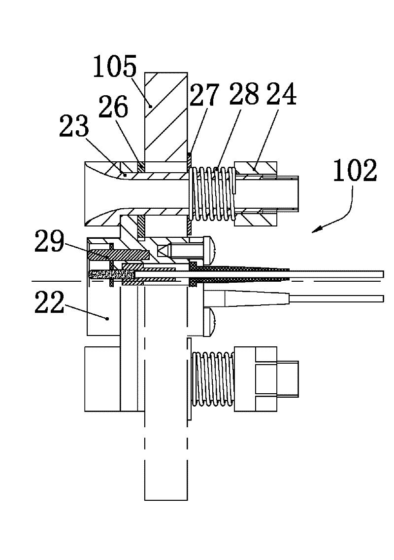
[0020] Embodiment 1 of the floating connector assembly, such as Figure 1-4 As shown, it consists of a fixed connector 101 and a floating connector 102.

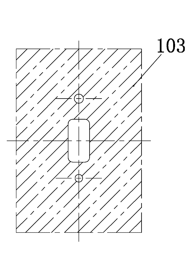
[0021] fixed connector 101 (as figure 1 ) has a fixed connector housing 11, and the fixed connector housing 11 is a square disc housing. The first guide post 15 and the second guide post 12 are equal. The unequal outer diameters of the two guide posts can effectively prevent mis-insertion with the floating connector 102. Both guide posts are stepped shafts with a large diameter section and a small diameter section. structure and form a step surface between their respective large and small diameter sections, the small diameter section of each guide column deviates from the plug-in end of the fixed connector and is provided with an external thread section, and the square plate of the fixed connector housing 11 is provided with two When the fixed connector 101 is in use, the fixed connector housing 11 is first assembled on th...


PUM


Abstract

The invention relates to a floating connector component and a floating connector of the floating connector component. The floating connector comprises a shell body; more than two guide devices matched with a adaptive connector in a guide positioning manner are arranged on the shell body along the axial direction and are matched with the shell body in an anti-movement manner along the radial direction; a floating section for being assembled on a corresponding mounting panel in a floating manner along the radial direction is arranged on each guide device, and an elastic device pressed and matched with the corresponding mounting panel is sleeved on the guide device; when in use, the floating connector can be assembled on the corresponding installation panel in a floating manner along the radial direction to realize the automatic aligning of the floating connector in the inserting process, thereby reducing the requirement for the matching precision between two moulds; and in addition, as the elastic device is sleeved on each guide device, the elastic device can be pressed and matched with the corresponding installation panel when the floating connector is connected with the matched connector, so that the floating connector assembled on the corresponding installation panel in a floating manner is kept at the original position, thereby reducing the automatic excursion generated by self gravity and other factors.

Description

technical field [0001] The invention relates to the field of electrical connectors, in particular to a floating connector assembly and a floating connector thereof. Background technique [0002] At present, product designs in fields such as optics and electricity are gradually becoming modularized and miniaturized. In the modular design, it mainly tends to be a cabinet structure. Specifically, various components are integrated and installed in a chassis to form a module. Connection; this connection method requires extremely high matching precision between the module chassis and the corresponding equipment rack, otherwise it may cause the connection between the module and the equipment to fail due to the coordination error between the module and the equipment; however, in practice In production, the coordination error between the chassis and the equipment rack is unavoidable, which hinders the development of product modularization and miniaturization. [0003] In order to r...

Claims


Application Information

Patent Timeline
Patent Type & Authority Applications(China)
IPC IPC(8): H01R13/631H01R13/74
Inventor 姚金恒
Owner CHINA AVIATION OPTICAL-ELECTRICAL TECH CO LTD
Why Eureka
Try Eureka