Conductor payoff rack

A pay-off frame and wire technology, which is applied to overhead lines/cable equipment, conveying filamentous materials, thin material handling, etc., can solve problems affecting work progress, construction safety hazards, and wire coil drop, etc., and is easy to promote , Improve work efficiency and ensure safety

Inactive Publication Date: 2012-04-04
LUOHE POWER SUPPLY OF HENAN ELECTRIC POWER CORP
View PDF6 Cites 23 Cited by
  • Summary
  • Abstract
  • Description
  • Claims
  • Application Information

AI Technical Summary

Problems solved by technology

[0002] At present, during the construction of transmission lines, when using traditional wire pay-off racks to lay out the wires, due to the limitation of the site, sometimes the ground is soft. In this process, the entire wire reel will slide to one side along the pay-off shaft due to the unbalanced force on the two pay-off frames. After the wire reel slides to one side, it will stick to the pay-off frame and cannot move, which will affect the progress of the work a

Method used


Image

  • Conductor payoff rack
  • Conductor payoff rack

Examples


Example Embodiment

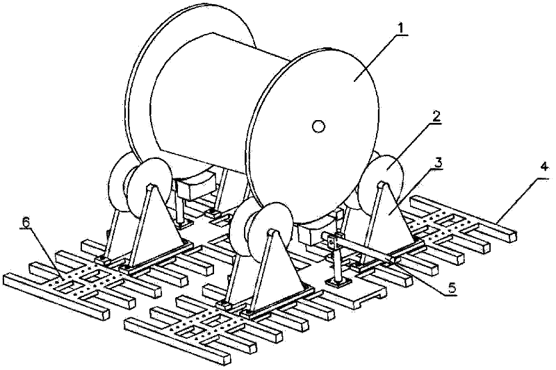
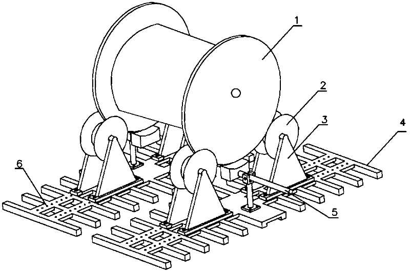
[0013] The embodiments of the present invention are further described below in conjunction with the drawings:

[0014] As shown in the drawings, the present invention is mainly composed of a roller 2, a bracket 3, a base 4, and a brake device 5. The four brackets 3 are respectively provided on the rollers 2 to support the wire reel. The four brackets 3 are divided into two groups, which are respectively placed on the two rows of bases 4, and the two brake devices 5 are placed under the wire reel, respectively installed in two rows On the base 4.

[0015] The bracket 3 is a regular triangle structure. Each pay-off bracket has three internal and external sub-brackets. The upper ends of the two sub-brackets are connected by a central axis. The lower part of the bracket is placed on the two main supports of the base 4 with perforations on both sides. The screw is inserted into the perforation to realize the connection with the base 4.

[0016] The roller 2 is of a concave type, the thi...


PUM


Abstract

The invention discloses a conductor payoff rack for a power transmission line, which comprises a conductor wheel disc, rollers, four support frames, two rows of bases and two sets of brake devices, wherein the conductor wheel disc is supported on the rollers on which the four support frames are arranged respectively; every two support frames are respectively placed on the two rows of bases; and the brake devices are arranged at the middle of the two rows of bases transversely spanning below the conductor wheel disc. Each brake device is of a lever type structure and comprises a pressing rod, a brake pad arranged at the inner end of the pressing rod and a pressing rod supporting rod; and the two sets of brake devices are wholly seated between the two groups of support frames and are respectively installed on the two bases. The conductor payoff rack has the beneficial effects that the limit of a traditional operation method is basically solved, and the safety coefficient in the operation is greatly improved; and the space between every two rollers is correspondingly adjusted according to conductor wheel discs with different diameters, so that the payoff and use requirements of a conductor wheel with common mass are satisfied. As the rollers, the support frames, the bases, the brake devices and other parts on the conductor payoff rack are easy to process and assemble and are easy to popularize in the electric construction, the work efficiency is improved, and the safety is ensured during the use, and therefore, the economic and social effects are remarkable.

Description

Technical field [0001] The invention relates to a power transmission line construction tool, in particular to a wire pay-off rack when the wires of the power transmission line are deployed. Background technique [0002] At present, during the construction of power transmission lines, when the traditional wire pay-off rack is used to unwind the wires, because of the limitation of the site, the geology is sometimes soft. Although the two pay-off racks are adjusted with hydraulic devices before the exhibition, the wires are in the process of unwinding. In the middle, due to the unbalanced force of the two pay-off racks, the entire wire reel will slide on one side along the pay-off shaft. After the wire reel slides to one side, it will stick to the pay-off rack and cannot move, which affects the work progress and is unsafe. . Sometimes, when the part of the rotating shaft and the wire pay-off rack rotates, the slipping phenomenon may occur. If the operator does not monitor well, the...

Claims


Application Information

Patent Timeline
IPC IPC(8): H02G1/02B65H49/00
Inventor 陈红卫殷志昂杨留柱刘洁王群营
Owner LUOHE POWER SUPPLY OF HENAN ELECTRIC POWER CORP
Why Eureka
Try Eureka