
Motor fixing support and assembling method thereof

A technology for motor fixing and installation slots, which is applied in the direction of electromechanical devices, manufacturing motor generators, casings/covers/supports, etc., can solve problems such as falling off, complicated operation, and increased additional costs, and achieve cost-saving effects

Inactive Publication Date: 2012-04-04
CHANGZHOU XINYA ELECTROMOTOR
View PDF5 Cites 0 Cited by
  • Summary
  • Abstract
  • Description
  • Claims
  • Application Information

AI Technical Summary

Problems solved by technology

[0002] The motor fixing bracket is composed of non-metallic parts and metal parts. Now most of them adopt interference fit or glue bonding or rivet riveting. The interference fit requires high dimensional accuracy, and the processing requirements for metal parts are high and assembly is relatively difficult. Difficult; when using glue for bonding, the glue is easy to age, combine and fall off, and the glue itself increases additional costs; when using rivets, the process is complicated, more equipment is required, the operation is complicated, and the rivets themselves increase additional costs
In addition, using the above method to combine non-metallic parts with metal parts often causes non-metallic parts to break, deform, move radially or axially, and fall off.

Method used


Image

  • Motor fixing support and assembling method thereof
  • Motor fixing support and assembling method thereof
  • Motor fixing support and assembling method thereof

Examples


Embodiment Construction

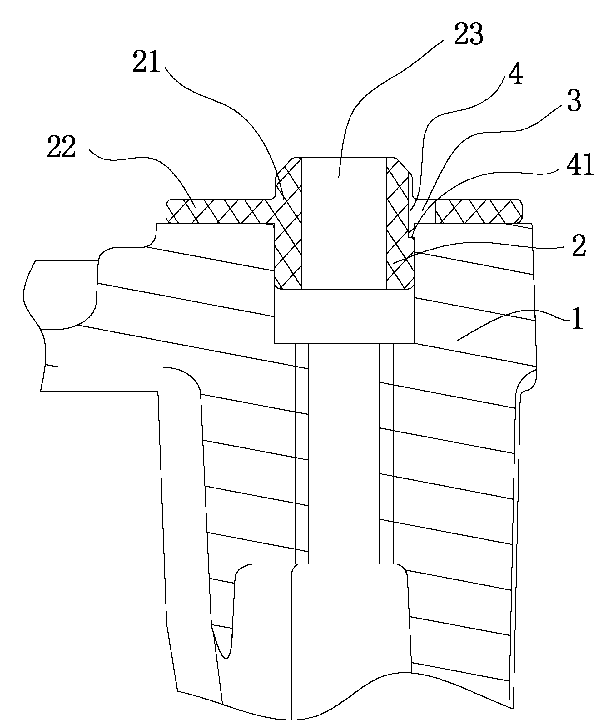
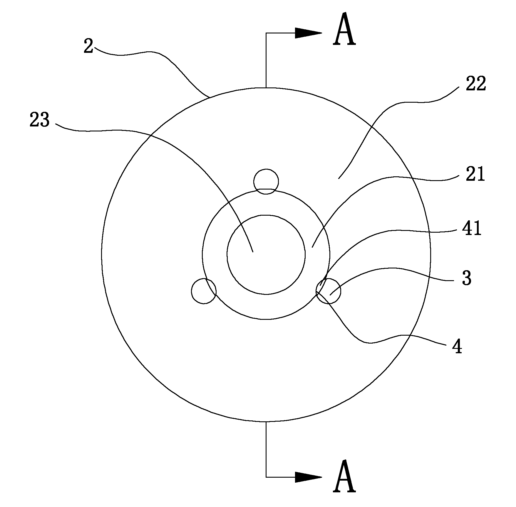
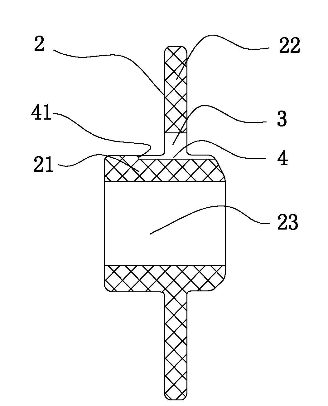
[0015] like Figure 1-Figure 4 The shown motor fixing bracket includes an end cover 1 and insulating mesons 2 installed on the surface of the end cover 1 . The material of the end cap 1 is non-ferrous metal, which may be aluminum alloy or iron; the material of the insulating meson 2 is plastic or nylon or rubber. The insulating meson 2 includes a main body 21 and a baffle 22 sleeved on the peripheral surface of the main body 21 , the baffle 22 is arranged in the middle of the main body 21 and has an integrated structure with the main body 21 .

[0016] like Figure 4 As shown, there are several installation grooves 11 on the surface of the end cover 1. The preferred embodiment of this case is to set four installation grooves 11 and be located at the edge of the end cover 1. Of course, the present invention is not limited to a definite number of installation grooves. Can be set according to needs. like figure 1 As shown, the body 21 corresponds to the shape and size of the ...


PUM


Abstract

The invention relates to a motor fixing support and an assembling method thereof. The motor fixing support comprises an end cover and an insulation muon arranged on the surface of the end cover. The insulation muon comprises a body and a baffle extending from the circumferential direction of the body towards the outside. An installation groove is arranged on the surface of the end cover, the bodycorresponds to the installation groove in shape and size, one end of the body is clamped in the installation groove, and the baffle is supported on the end face of the installation groove. At least one through hole is arranged at the connection position of the baffle and the body, a positioning groove axially extending along the through hole is arranged on a connection section of the outer wall of the body and the through hole, one end of the positioning groove facing to the end cover extends out of the through hole and the end face of the end forms a step, and the groove wall of the installation groove is clamped on the step. Non-metal pieces and metal pieces of the motor fixing support are stably connected, and the non-metal pieces do not crack, deform, generate radial or axial movement, or fall off.

Description

technical field [0001] The invention relates to a motor fixing bracket for installing a motor on another object and an assembly method thereof. Background technique [0002] The motor fixing bracket is composed of non-metallic parts and metal parts. Now most of them adopt interference fit or glue bonding or rivet riveting. The interference fit requires high dimensional accuracy, and the processing requirements for metal parts are high and assembly is relatively difficult. Difficult; when glue is used for bonding, the glue is easy to age, combine and fall off, and the glue itself increases additional costs; when using rivets, the process is complicated, more equipment is required, the operation is complicated, and the rivets themselves increase additional costs. In addition, using the above method to combine non-metallic parts with metal parts often causes the non-metallic parts to break, deform, move radially or axially, and fall off. Contents of the invention [0003] Th...

Claims


Application Information

Patent Timeline
Patent Type & Authority Applications(China)
IPC IPC(8): H02K5/00H02K15/14
Inventor 周勃然薛海诚
Owner CHANGZHOU XINYA ELECTROMOTOR
Learn More