Steam cleaning device

A technology for cleaners and steam generators, applied in the field of steam cleaners, to achieve the effect of high mechanical stability

Active Publication Date: 2012-04-04
ALFRED KARCHER GMBH & CO KG
View PDF7 Cites 0 Cited by
  • Summary
  • Abstract
  • Description
  • Claims
  • Application Information

AI Technical Summary

Problems solved by technology

However, such fixation is associated with high manufacturing and assembly costs

Method used


Image

  • Steam cleaning device
  • Steam cleaning device
  • Steam cleaning device

Examples


Embodiment Construction

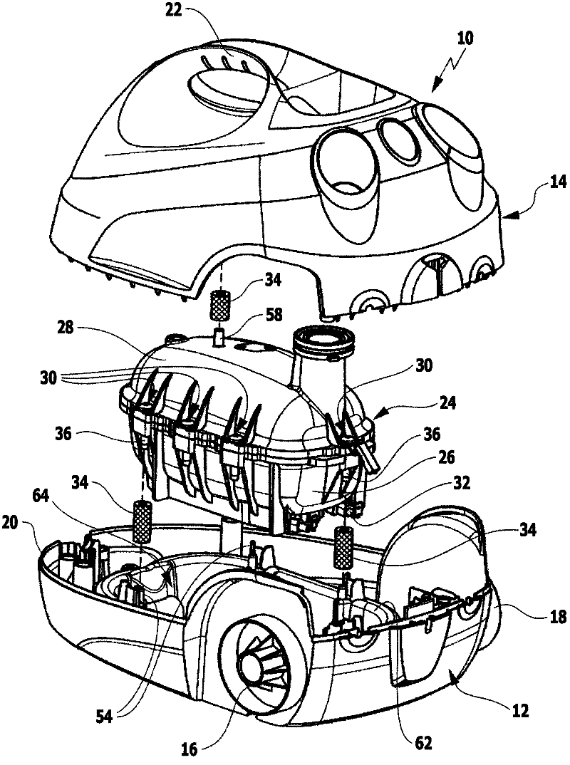
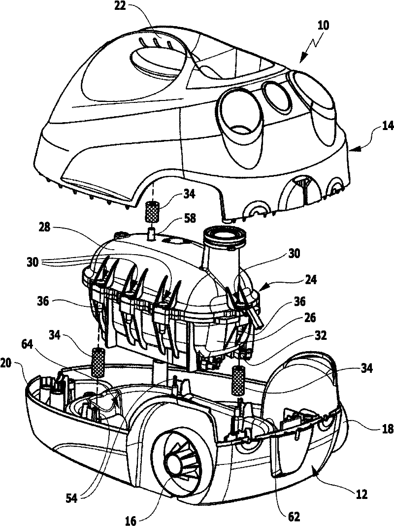
[0027] A steam cleaner 10 is shown schematically in the drawing with a two-part housing comprising a housing lower part 12 and a housing upper part 14 . On the housing lower part 12 are formed outer wheel holders 16 , 18 facing away from one another, on which a respective impeller is rotatably mounted. In addition, deflection rollers can be fastened on the underside of the housing lower part 12 at a distance from the two wheel receptacles 16 , 18 . Such deflection rollers are known to those skilled in the art. The deflection rollers are therefore not shown in the figures for a better overview.

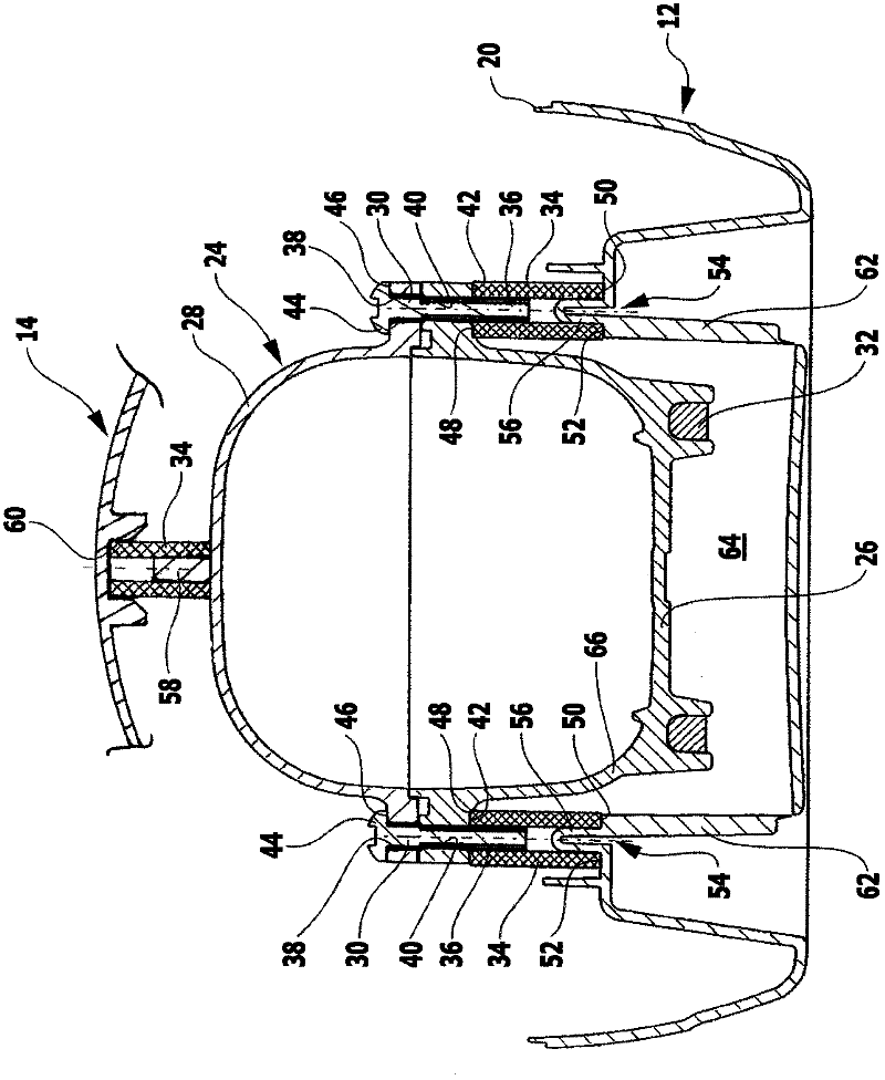
[0028] The housing upper part 14 can rest on the surrounding edge 20 of the housing lower part 12 . The upper housing part 14 forms a handle 22 which can be grasped by a user for carrying the steam cleaner 10 .

[0029] Housing bottom part 12 and housing top part 14 accommodate an electrically heatable steam generator 24 between them. The steam generator comprises a generator lower...


PUM


Abstract

The invention relates to a steam cleaning device, comprising a housing, which has an upper housing part (14) and a lower housing part (12), between which a boiler (24) that can be electrically heated is disposed for generating steam, which can be applied to a surface to be cleaned. The boiler comprises an upper boiler part (28) and a lower boiler part (26), which are screwed together by connecting screws (30), and the boiler is supported on support elements (54) of the lower housing part. In order to reduce the production and installation costs for fixing the boiler to the lower housing part, at least some of said screws are connected to a support element (54) by means of a vibration-damping, thermally insulating carrier part (34).

Description

technical field [0001] The invention relates to a steam cleaner with a housing having an upper housing part and a lower housing part, between which an electrically heatable steam generator is arranged, For generating steam that can be applied to the surface to be cleaned, wherein the steam generator comprises an upper part of the generator and a lower part of the generator, the upper part of the generator and the lower part of the generator are screwed together by connecting bolts, and wherein the steam generation The device is supported at the support element of the lower part of the housing. Background technique [0002] This steam cleaner is used for cleaning a wide variety of surfaces, especially hard surfaces. This steam cleaner includes an electrically heatable steam generator for evaporating liquid cleaning agents. The steam generated can be applied to the surface to be cleaned, for example the floor. [0003] The steam generator has a considerable temperature duri...

Claims


Application Information

Patent Timeline
Patent Type & Authority Applications(China)
IPC IPC(8): B08B3/02F16F1/373
CPCF22B1/284F22B37/246B08B3/026B08B2230/01
Inventor 米夏埃尔·荀内瓦尔德托比亚斯·杜克斯
Owner ALFRED KARCHER GMBH & CO KG
Why Eureka
Try Eureka