
Drilling reamer

A technology of drilling reamer and tool handle, which is applied in the direction of repairing drill, drilling tool accessories, drilling/drilling equipment, etc. Use a wide range of effects

Inactive Publication Date: 2012-04-11
张灵娟
View PDF0 Cites 2 Cited by
  • Summary
  • Abstract
  • Description
  • Claims
  • Application Information

AI Technical Summary

Problems solved by technology

[0002] The drill bit and the reamer of the existing drill reamer are of an integrated structure, which cannot be disassembled, and can only be used for simultaneous drilling and reaming, and the scope of use is narrow
Moreover, the drill bit is the first stress-bearing part, which is easy to be damaged and needs to be sharpened frequently, while the reamer part often hinders sharpening, which brings difficulties

Method used


Image

  • Drilling reamer
  • Drilling reamer
  • Drilling reamer

Examples


Embodiment Construction

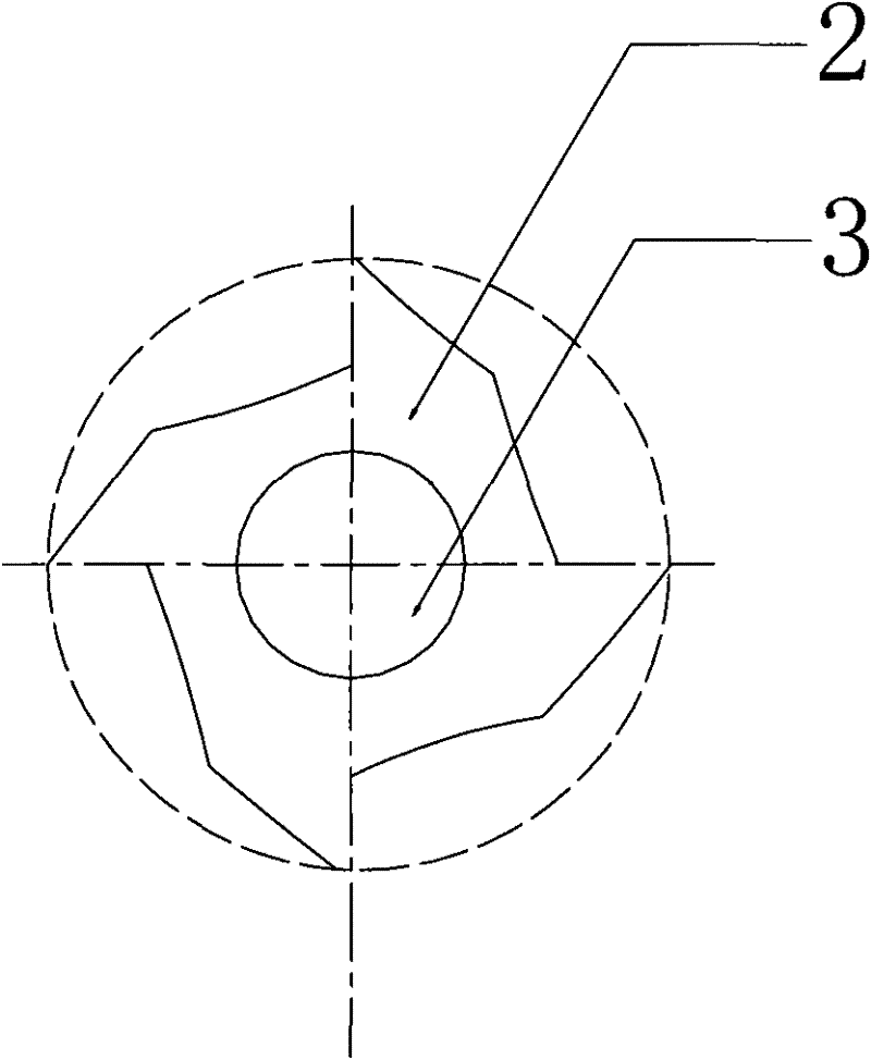
[0012] Such as figure 1 and figure 2 As shown, a drill reamer includes a handle 1 and a cutter head 2, the cutter head 2 is arranged on one end of the handle 1, the transverse centerline of the cutter head 2 overlaps with the transverse centerline of the handle 1, and There is a threaded hole 3 on the head 2 along its transverse center line, and the threaded hole 3 leads to the handle 1. Through the threaded hole 3, the drill bit can be easily fixed on the handle 1. When it is necessary to sharpen the knife or replace the drill bit It is also very convenient to disassemble; in order to enhance the stability of the drill bit, a clamping hole 4 communicating with the threaded hole 3 is provided on the handle 1, and the centerline of the clamping hole 4 and the centerline of the threaded hole 3 are perpendicular to each other.


PUM


Abstract

The invention relates to a drilling reamer comprising a tool holder and a tool bit, wherein the tool bit is arranged on one end of the tool holder, and the horizontal center line of the tool bit is overlapped with that of the tool holder. The drilling reamer is characterized in that the tool bit is provided with a threaded hole along the horizontal center line, and the threaded hole is led to the inside of the tool holder. The drilling reamer is wide in application range and convenient to sharpen, and a drill bit is replaceable.

Description

technical field [0001] The invention relates to a reamer, in particular to a drill reamer, which belongs to a compound tool. Background technique [0002] The drill bit and the reamer of the existing drilling reamer are of an integral structure, cannot be disassembled, can only be used for drilling and reaming synchronously, and have a narrow range of use. Moreover, the drill bit is the first stress-bearing part, which is easy to damage and needs to be sharpened frequently, while the reamer part often hinders sharpening, which brings difficulties with sharpening. Therefore, a new technical solution is needed to solve the above technical problems. Contents of the invention [0003] The purpose of the present invention is to provide a drill reamer with wide application range, removable drill bit and convenient sharpening. [0004] The technical scheme adopted in the present invention is: [0005] A drill reamer, comprising a handle and a cutter head, the cutter head is ar...

Claims


Application Information

Patent Timeline
Patent Type & Authority Applications(China)
IPC IPC(8): B23B51/08
Inventor 张灵娟
Owner 张灵娟
Learn More