
Shock tunnel detonation double-driving method and device

A technology of shock wave wind tunnel and detonation, which is applied in the direction of measuring devices, ground devices, transportation and packaging, etc., can solve the problems of large diaphragm damage, weak driving ability, and affecting the reliability of wind tunnel tests, etc., to achieve interference Small size, high driving capacity, effect of improving flow quality

Active Publication Date: 2013-12-04
INST OF MECHANICS - CHINESE ACAD OF SCI
View PDF3 Cites 0 Cited by
  • Summary
  • Abstract
  • Description
  • Claims
  • Application Information

AI Technical Summary

Problems solved by technology

[0004] The above-mentioned positive detonation driving energy is large and the driving ability is strong, but the flow quality is affected by the Taylor sparse wave after the detonation wave, and it has a great damage to the diaphragm between the driving section and the driven section, which affects the wind tunnel. The reliability of the test; while the flow quality of the reverse detonation drive is good, the diaphragm rupture is good, but the driving ability is weaker than the forward detonation drive

Method used


Image

  • Shock tunnel detonation double-driving method and device

Examples


Embodiment Construction

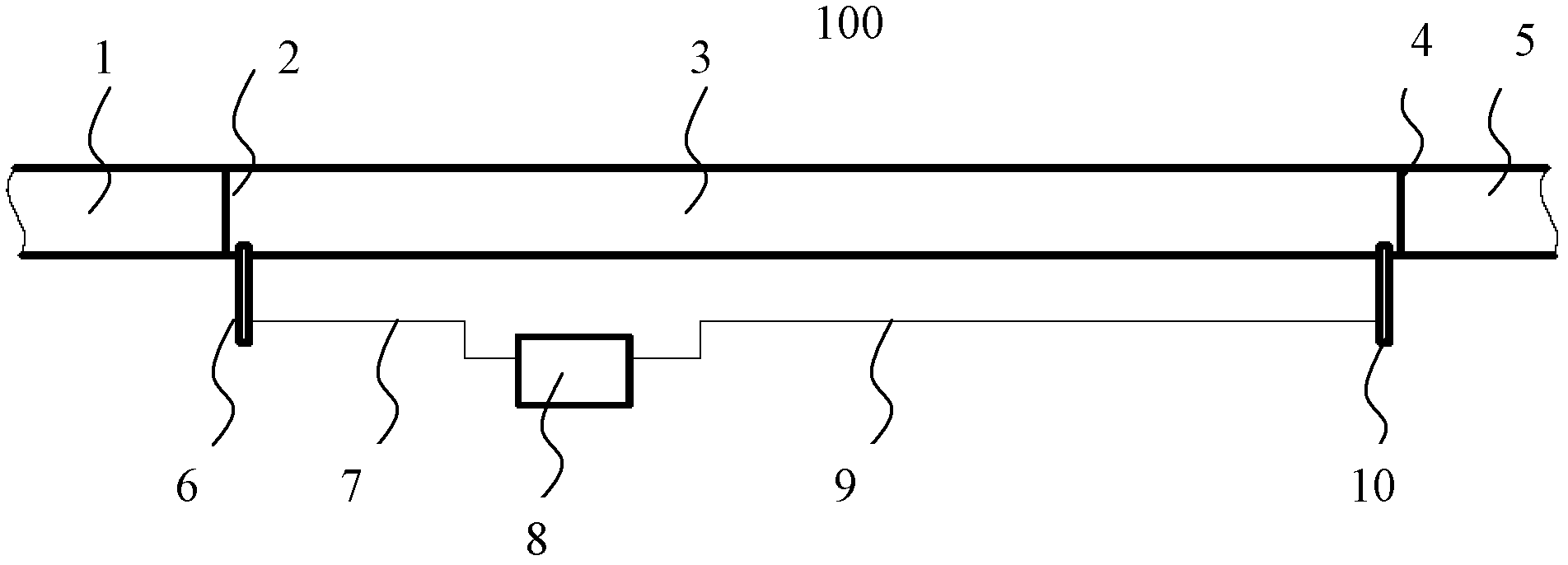
[0017] figure 1 It is a structural schematic diagram of the detonation dual-drive device of the present invention.

[0018] Such as figure 1 As shown, the detonation double-driven device of the present invention includes: a shock tunnel 100, the shock tunnel 100 has a detonation driving section 3, one end of the detonation driving section 3 is provided with an unloading section 1, and the other end is provided with a The driven section 5, the first diaphragm 2 is arranged between the detonation section 1 and the detonation driving section 3, and the second diaphragm 4 is arranged between the driven section 5 and the detonation driving section 3. A forward detonation driving ignition device 6 is provided at one end of the detonation driving section 3 close to the detonation section 1 , and a reverse detonation driving ignition device 10 is provided at the end of the detonation driving section 3 close to the driven section 5 . A controllable delay trigger 8 is connected betwee...


PUM


Abstract

The invention discloses a shock tunnel detonation double-driving method, which comprises the following steps of: 1) arranging a positive detonation igniter at one end close to an explosion-releasing section, of a shock tunnel detonation driving section and arranging a reverse detonation driving igniter at the end close to a driven section, of the detonation driving section; 2) igniting by the positive detonation igniter, thereby forming a positive driving detonation wave; 3) after transmitting the positive driving detonation wave along the detonation driving section for a preset period of time, igniting by the reverse detonation driving igniter, thereby forming a reverse driving detonation wave; and 4) tearing a diaphragm arranged between the driven section and the detonation driving section by the reverse driving detonation wave and forming a motion shock wave after intersecting the positive driving detonation wave with the reverse driving detonation wave. According to the method, the diaphragm arranged between the driven section and the detonation driving section is torn by the reverse driving detonation wave, the diaphragm is more regularly torn and a diaphragm fragment is difficult to form, thereby being small in interference effect on the flowing of the formed airflow and promoting the flowing quality of the driven air.

Description

technical field [0001] The invention relates to a technique for the experimental research of an air-breathing high-speed aircraft, in particular to a shock tunnel detonation driving method and device for ground simulation equipment of a hypersonic aircraft. Background technique [0002] During the development of a hypersonic vehicle, a large number of ground simulation experiments are required to obtain data on the aerodynamic force and propulsion performance of the vehicle. The pulse-type shock tunnel is an effective ground test equipment for simulating hypersonic flight flow, and has been widely used in related research. The detonation-driven shock tunnel uses the high-temperature and high-pressure gas formed by the detonation of combustible gas to do work, forming a high-intensity shock wave to drive the driven section of the shock tunnel to simulate the hypersonic flow of the test gas in the driven section to achieve sufficient total enthalpy. . [0003] The detonation...

Claims


Application Information

Patent Timeline
Patent Type & Authority Patents(China)
IPC IPC(8): B64F5/00G01M9/02B64F5/60
Inventor 姜宗林赵伟陈宏林建民俞鸿儒
Owner INST OF MECHANICS - CHINESE ACAD OF SCI
Learn More