Device and method for positioning sensing element of displacement sensor

A displacement sensor and sensing element technology, applied in measuring devices, instruments, etc., can solve the problems of reducing industrial production efficiency, reducing the one-time pass rate of sensing element installation and positioning process, and increasing measurement error, so as to improve the process level and production efficiency , Improve the first pass rate and reliability, and improve the effect of measurement accuracy

Active Publication Date: 2012-04-11
江门市英合创展电子有限公司
View PDF3 Cites 2 Cited by
  • Summary
  • Abstract
  • Description
  • Claims
  • Application Information

AI Technical Summary

Problems solved by technology

[0002] At present, because there is no effective positioning device for the sensing element of the displacement sensor, when installing the sensing element of the sensor, after coating the sensing element with glue, the sensing element will be cured by the glue before the glue is cured due to the lack of a fixing device. The displacement occurs due to shrinkage and creep during the time, which cannot guarantee the accuracy of the position installation of the sensing element, which makes the technological level of the existing technology low, which not only reduces the efficiency of industrial production, but also because the sensing element moves during the curing process of the glue. After the glue is cured, the installation position of the sensing element does not meet the requirements, which reduces the first pass rate of the sensing element installation and positioning process, and also reduces the reliability of the sensing element, which increases the measurement error of the product
In addition, the installation and positioning of the current sensing element cannot be adjusted and positioned according to products with different ranges, which greatly limits the application of the same sensor in the production and detection of products with different ranges

Method used


Image

  • Device and method for positioning sensing element of displacement sensor
  • Device and method for positioning sensing element of displacement sensor
  • Device and method for positioning sensing element of displacement sensor

Examples


Embodiment Construction

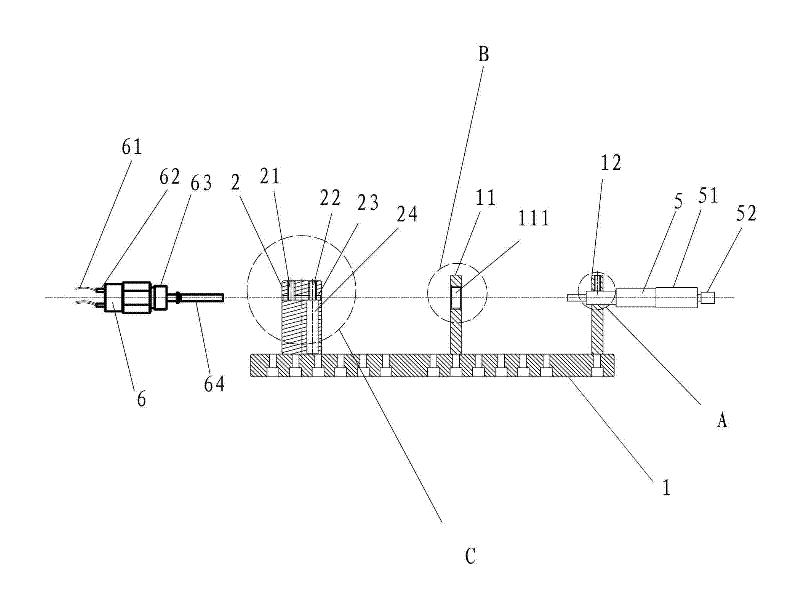
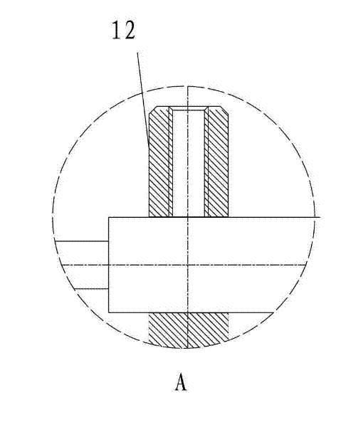
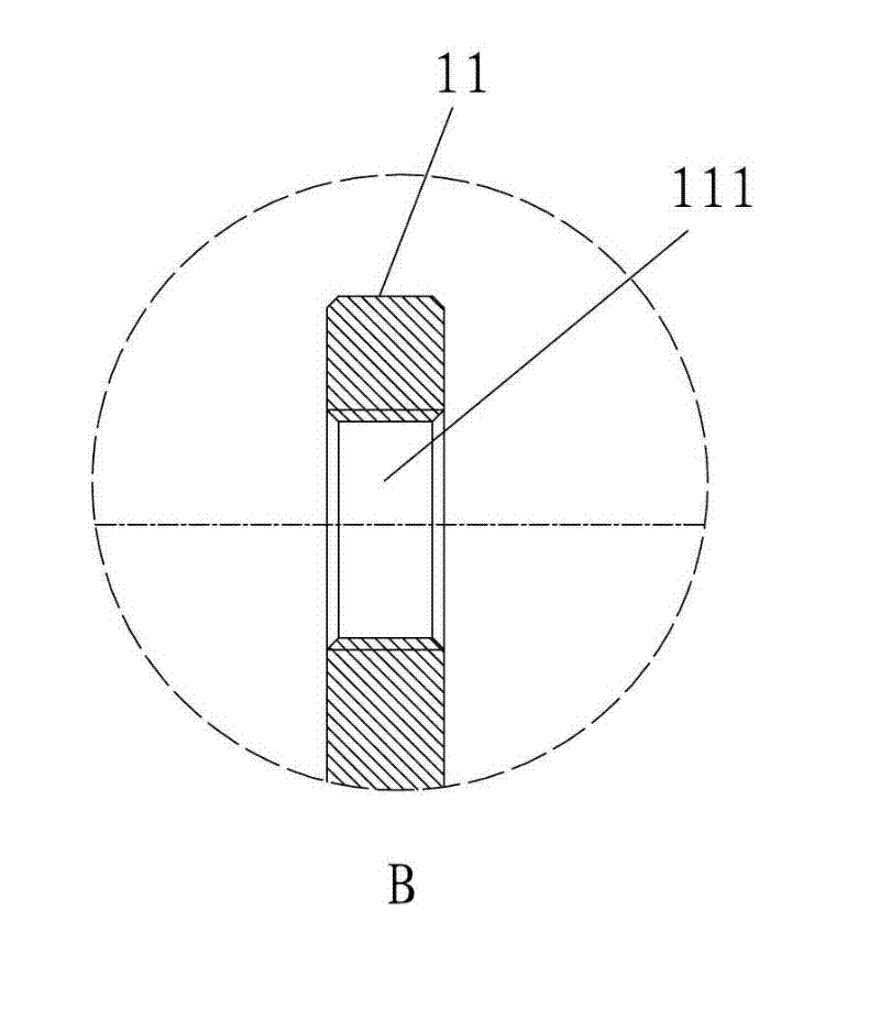
[0018] refer to Figure 1 to Figure 4 , a positioning device for a displacement sensor inductive element of the present invention, which includes a base 1, on which a lead fixing frame 2, a sensor fixing plate 11 and a measuring instrument fixing plate 12 are vertically arranged from left to right, The base 1 is integrally cast with the sensor fixing plate 11 and the measuring instrument fixing plate 12, and the base 1 is molded by one-time casting, the process is simple, and the operation is convenient. A displacement measuring instrument is welded in the through hole of the measuring instrument fixing plate 12 for accurately setting the installation position of the sensing element 62 . The sensor fixing plate 11 is drilled with a screw hole 111 for installing the sensor (inductive element to be installed), so that the sensor 6 to be installed with the inductive element can be installed on the base 1 conveniently, quickly and simply; The lead wire fixing frame 2 is fixedly i...


PUM


Abstract

The invention discloses a device and method for positioning a sensing element of a displacement sensor. The device comprises a base, wherein a lead fixing frame, a sensor fixing plate and a measurer fixing plate are vertically arranged on the base from left to right; a displacement measurer is arranged on the measurer fixing plate; and a left screw hole, a right screw hole, a through hole and a lead accommodation hole for accommodating a sensing element lead are formed in the lead fixing frame. A stud in the right screw hole is rotated to downwards press the sensing element lead and drag the sensing element to uniformly move with a tiny span; and meanwhile, a meter display plate is observed until the sensing element is moved to a set position. By the device and the method, the sensing element of the displacement sensor can be precisely arranged and positioned at the set position; the device has a simple structure, is convenient to operate and can effectively guarantee the one-time pass rate and the reliability of a positioning process, so the measurement precision of a product is improved; and therefore, the device and the method can be widely applied to installation and positioning of the sensing element of the displacement sensor.

Description

technical field [0001] The invention relates to a positioning device for an inductive element of a displacement sensor and a positioning method for positioning the inductive element by using the positioning device. Background technique [0002] At present, because there is no effective positioning device for the sensing element of the displacement sensor, when installing the sensing element of the sensor, after coating the sensing element with glue, the sensing element will be cured by the glue before the glue is cured due to the lack of a fixing device. The displacement occurs due to shrinkage and creep during the time, which cannot guarantee the accuracy of the position installation of the sensing element, which makes the technological level of the existing technology low, which not only reduces the efficiency of industrial production, but also because the sensing element moves during the curing process of the glue. After the glue is cured, the installation position of the...

Claims


Application Information

Patent Timeline
Patent Type & Authority Applications(China)
IPC IPC(8): G01B21/02
Inventor 陈文轩林锦新
Owner 江门市英合创展电子有限公司
Why Eureka
Try Eureka