LED display system having pulse scattering mode and method thereof

A display system and LED lamp technology, applied in static indicators, lighting devices, light sources, etc., can solve the problems of brightness loss, constant brightness calculation, uneven brightness feeling, etc., and achieve the effect of reducing flicker and brightness loss.

Inactive Publication Date: 2012-04-11
苏州君嬴电子科技有限公司
View PDF2 Cites 11 Cited by
  • Summary
  • Abstract
  • Description
  • Claims
  • Application Information

AI Technical Summary

Problems solved by technology

[0015] ② The luminance information of the high bits of the 10-bit grayscale value will be displayed intensively. For example, the effective display time of the high 3 bits accounts for 1 / 2 of the total time T_FRAM, which will make the brightness of the human eye feel very uneven, resulting in uneven color in the whole screen. soft
Therefore, the concept of pulse breaking is introduced. The 10-bit gray value of D[0:9] can be sorted on average, and the upper 2 bits D[8:9] of the 10-bit gray value can be split into 2 and 4 times respectively. Display and shift, the lower 8 bits of grayscale D[0:7] are not split, such as displaying in the following order: D[9], D[8], D[1], D[5], D[ 9], D[2], D[6], D[9], D[8], D[0], D[4], D[9], D[3], D[7], but the brightness The calculation remains unchanged, but there is still a large loss of brightness

Method used


Image

  • LED display system having pulse scattering mode and method thereof
  • LED display system having pulse scattering mode and method thereof
  • LED display system having pulse scattering mode and method thereof

Examples


Embodiment Construction

[0055] The content of the present invention will be further described below in conjunction with the LED display system.

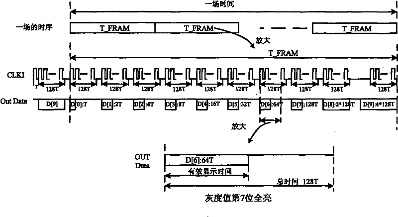
[0056] figure 1 It is a schematic diagram of the timing of the traditional LED pulse display mode. Such as figure 1 As shown, in the shown T_FRAM time, a total of 10 times of display and shift are required, and the total time of T_FRAM is about 14*256T; in this T_FRAM, the brightness of a certain LED light is calculated as follows:

[0057] D[0]*1T+D[1]*2T+D[2]*4T+D[3]*8T+D[4]*16T+D[5]*32T+D[6]*64T+D [7]*128T+D[8]*2*128T+D[9]*4*128T.

[0058] It can be seen from the above: ①When a certain LED light is the brightest, its effective display time is (8*128-1)T, which is less than 14*128T of T_FRAM, and the brightness loss is greater than 40%; ②The high bit of the 10-bit gray value For example, the effective display time of the upper 3 bits accounts for 1 / 2 of the total time T_FRAM, which will make the brightness of the human eye feel very uneven, resulting ...


PUM


Abstract

The invention relates to an LED display system having a pulse scattering mode and a method thereof. The system comprises an LED controller and a plurality of LED unit plates that are in series connection. Each of the LED unit plate respectively includes an LED drive board and a plurality of LED lamps. The LED controller emits a data signal and a control signal. An array D [ 0: (H-1)] is used to express H bit gray values of an LED lamp of a drive of a certain end and the D [ 0 ] is used to express a lowest bit value of the H bit gray values. The D [ 0: (H-1)] is split into a high bit D [ ( H-n) : ( H-1) ] and a low bit D [ 0 : ( H-n-1) ]. The high bit is split into m * 2 <n>-times, m * 2 <n-1>-times . . . or m*2-times display and shift within a certain time, wherein the time is equal to a result of m * T_ FRAM. The low bit is fused and is expressed by an expression of m * D [ 0: ( H-n-1) ]. And the formula of the scattering formula is expressed as follows: m * D [ 0 : ( H-1) ] = m * ( 2 <n > * 2 <H-n-1> * T + 2 <H-n-1> * T + . . . + 2 * 2 <H-n-1> * T ) + m * D [0:( H-n-1) ]. According to the invention, more uniform brightness is provided; scintillation is obviously reduced; and brightness losses can be substantially reduced; moreover, different system application demands can be met by using different splitting modes.

Description

technical field [0001] The invention relates to the technical field of LED display, in particular to an LED display system with a pulse breaking method. Background technique [0002] The luminescent material of the LED display is a light-emitting diode. The forward volt-ampere characteristics of the light-emitting diode are roughly the same as those of ordinary diodes. There is no current before the opening point of the voltage. The volt-ampere characteristic of the LED is approximately linear from the conduction to the safe maximum current. That is, in this region, the luminous intensity of the LED is approximately proportional to its current intensity, and the brightness of the light-emitting diode can be controlled by controlling the current. [0003] Generally speaking, there are usually two methods to control the brightness of LEDs: current control method and conduction time control method. The current control method is to control the brightness by adjusting the forwa...

Claims


Application Information

Patent Timeline
Patent Type & Authority Applications(China)
IPC IPC(8): G09G3/32H05B37/02
CPCY02B20/42Y02B20/40
Inventor 陈日仪张世侨赵启永斯斐霞
Owner 苏州君嬴电子科技有限公司
Why Eureka
Try Eureka