
Laminated machine and electrical core laminated mechanism

A stacking machine and stacking technology, applied in the direction of non-aqueous electrolyte battery, electrolyte battery manufacturing, sustainable manufacturing/processing, etc., can solve the problems of increasing equipment cost, affecting response speed, reducing stacking efficiency, etc., to reduce equipment cost, response time reduction, reduced motion interference or poor fit effects

Active Publication Date: 2012-04-11
肇庆兆阳装备技术有限公司
View PDF5 Cites 37 Cited by
  • Summary
  • Abstract
  • Description
  • Claims
  • Application Information

AI Technical Summary

Problems solved by technology

[0003] However, the operation of the positive electrode and the negative electrode are controlled by independent power sources. On the one hand, various actions such as suction, movement, and stacking of the electrodes need to cooperate with each other and depend on each other. The method will affect the response speed of each action to a certain extent and reduce the lamination efficiency. On the other hand, more power sources obviously increase the equipment cost

Method used


Image

  • Laminated machine and electrical core laminated mechanism
  • Laminated machine and electrical core laminated mechanism
  • Laminated machine and electrical core laminated mechanism

Examples


Embodiment 1

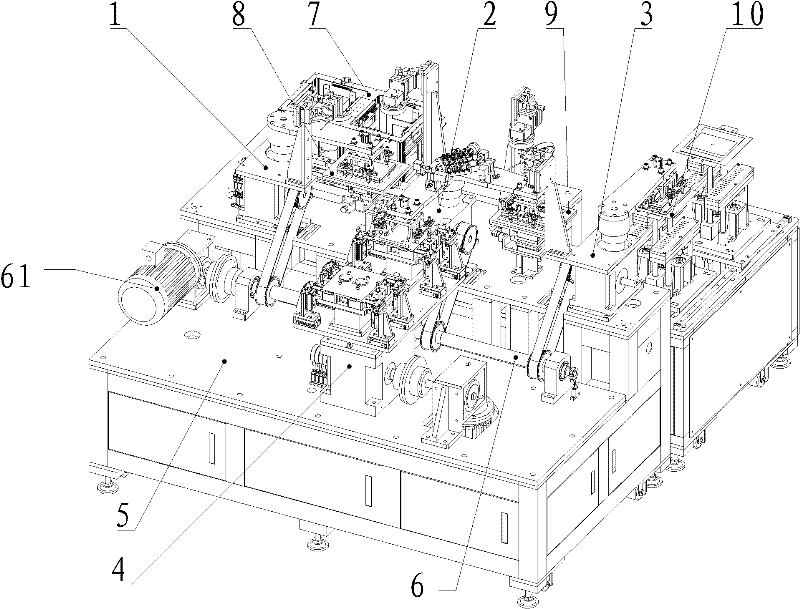
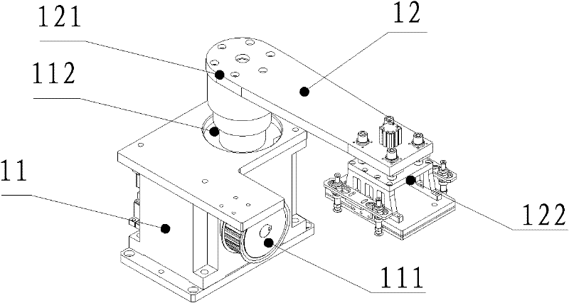
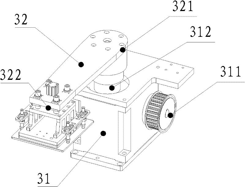
[0024] Please refer to figure 1 , the stacker of the present embodiment comprises the first magazine 7, the second magazine 10, the first positioning platform 8, the second positioning platform 9, the stacking platform 4 with at least one stacking position 41, the first material taking The manipulator 1, the second reclaiming manipulator 3, the lamination manipulator 2 and the lamination driving assembly may also include a base 5 for supporting and fixing the above components.

[0025] The first material box 7 and the second material box 10 are respectively used to provide different types of material sheets to be stacked, such as in the lamination process of power lithium battery cells, the first material box 7 provides the positive electrode sheet, and the second material box 10 provides the negative electrode sheet, and the two material boxes can be set in fixed positions respectively, and can also be set in the transmission mechanism so as to transport the material sheet fr...


PUM


Abstract

The invention discloses a laminated machine and an electrical core laminated mechanism, the laminated machine comprises a first material box, a second material box, a first positioning bench, a second positioning bench and a laminated bench possessing at least one lamination position, and also comprises a first material taking manipulator used for moving a first material sheet of the first material box to the first positioning bench, a second material taking manipulator used for moving a second material sheet of the second material box to the second positioning bench, a laminated manipulator used for moving the first material sheet of the first positioning bench, and / or the second material sheet of the second positioning bench to the laminated position, and a laminated drive component used for driving the first material taking manipulator, the second material taking manipulator and the laminated manipulator. The laminated machine employs laminated drive component with same power supply for driving the first laminated drive component, the second laminated drive component and laminated manipulator to realize the operation of material taking, moving and laminating. The lamination efficiency and technology quality can be effectively enhanced, the equipment cost can be reduced, and the technology can be simplified.

Description

technical field [0001] The invention relates to the field of battery manufacturing, in particular to a stacking machine and a cell stacking mechanism. Background technique [0002] In the manufacturing process of large-scale lithium-ion power batteries, a stacker is usually used to stack the positive and negative electrodes at intervals to form battery cells. In the commonly used lithium-ion battery cell stacking machine, first use the suction cup to absorb the positive electrode or negative electrode from the material box, and move it to the corresponding positioning table (usually called the secondary positioning table), when the electrode sheet needs to be stacked Use the suction cup to pick up the pole piece from the positioning table again, and move it to the stacking table to complete the stacking. During the entire stacking process, the operation of the positive and negative plates is controlled by different power sources and drive mechanisms. For example, different ...

Claims


Application Information

Patent Timeline
IPC IPC(8): H01M10/058
CPCY02E60/12Y02E60/10Y02P70/50
Inventor 骆承华范方才阳如坤
Owner 肇庆兆阳装备技术有限公司
Learn More