
Lighting Device

A technology for lighting devices and irradiation ranges, applied in lighting devices, energy-saving lighting, electric lamp circuit layout, etc., can solve the problems of not being able to feel enough brightness, lighting device 610 consumes power, and reduces power consumption, so as to improve visibility Effect

Inactive Publication Date: 2012-04-11
PANASONIC CORP
View PDF5 Cites 13 Cited by
  • Summary
  • Abstract
  • Description
  • Claims
  • Application Information

AI Technical Summary

Problems solved by technology

[0013] Even if the lighting device 610 designs the light source unit 61 based on the light beam, illuminance, luminance, and other photometric values ​​based on the visibility in the state of photopic vision, human eyes may not be able to perceive enough light in intermediate vision. Brightness
In addition, when the lighting control of the lighting device 610 is simply performed at an illuminance that is sufficiently bright to be perceived by humans, the lighting device 610 may consume unnecessary power.
Therefore, if the visibility of the light irradiated from the light source unit 61 is improved in the lighting device 610, power consumption may be reduced as a result.

Method used


Image

  • Lighting Device
  • Lighting Device
  • Lighting Device

Examples


Embodiment approach 1

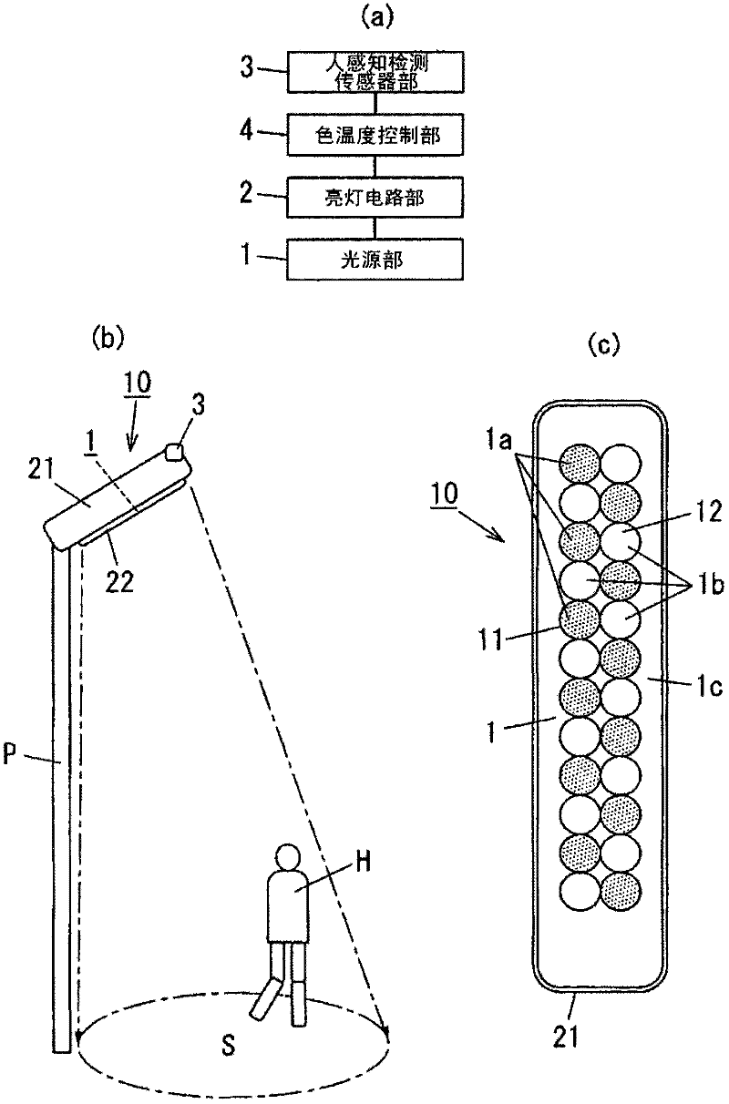
[0038] Below, use figure 1 as well as figure 2 The lighting device of this embodiment will be described.

[0039] Such as figure 1 As shown, the lighting device 10 of the present embodiment includes: a lighting circuit part 2, the lighting circuit part 2 lights the light source part 1 and connects it to an external commercial power supply, etc. Irradiate light; Human perception detection sensor part 3, this human perception detection sensor part 3 at least detects the existence of the person (for example, pedestrian H) in the irradiation range S; Color temperature control part 4, this color temperature control part 4 is not passed through above When the presence of the pedestrian H is detected by the human perception detection sensor part 3, the light irradiated by the light source part 1 is controlled to a first color temperature (for example, daylight color (day white)), and when the presence of the pedestrian H is detected by the human perception detection sensor part ...

Embodiment approach 2

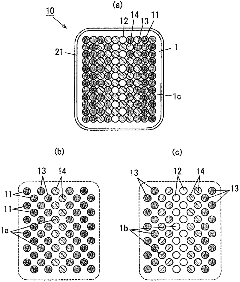
[0081] The lighting device 10 of this embodiment is different in that instead of figure 1 The light source unit 1 having two types of light-emitting devices 11 and 12 according to Embodiment 1 shown uses image 3 Shown is a light source unit 1 having a plurality of (here four) light emitting devices 11 , 12 , 13 , 14 . In addition, the same code|symbol is attached|subjected to the same component as Embodiment 1, and description is abbreviate|omitted suitably.

[0082] The light source unit 1 used in the lighting device 10 of the present embodiment is, for example, image 3 As shown in (a), in the lamp main body 21 , a plurality of light emitting devices 11 , 12 , 13 , 14 are arranged as the light source unit 1 on one surface side of a rectangular wiring board 1 c. The light source unit 1 of the lighting device 10 holds at least the first light source 1a (refer to image 3 (b)) and the second light source 1b (refer to image 3 (c)) The second light source 1b irradiates lig...


PUM


Abstract

The invention provides a lighting device improving the visibility based on radiating light further. The lighting device is provides a lamp lighting circuit part (2) lighting a light source part (1) of radiating light in a predetermined radiating range (S); a human sensing detecting sensor part (3) sensing the existence of a pedestrian (H) in at least the above radiating range (S); and a color temperature control part (4). When the human sensing detecting sensor part (3) detects no existence of the pedestrian (H), the color temperature control part (4) controls the radiating light to be in a first color temperature. When the human sensing detecting sensor part (3) detects the existence of the pedestrian (H), the color temperature control part (4) controls the radiating light to be in a second color temperature lower than the first color temperature.

Description

technical field [0001] The present invention relates to a lighting device that detects the presence of a person and switches lighting. Background technique [0002] In recent years, along with the conclusion and entry into force of the "Kyoto Protocol", people have sought to significantly reduce the emission of greenhouse gases, and have vigorously promoted the reduction of power consumption of various electrical equipment. Therefore, lighting devices used for outdoor public lighting such as street lamps and road lighting fixtures for securing pedestrian safety, etc. are no exception, and further reduction in power consumption is sought. [0003] As such lighting device 610, for example, as Figure 6 As shown, the following device is known. The device has: a light source unit 61 that irradiates light within a predetermined irradiation range; a lighting circuit unit 62 that supplies light for turning on the light source unit 61; Electric power of the lamp; the illuminance co...

Claims


Application Information

Patent Timeline
Patent Type & Authority Applications(China)
IPC IPC(8): H05B37/02
CPCY02B20/72Y02B20/44Y02B20/40
Inventor 户田直宏斋藤孝野口公喜槻谷绫子西冈浩二高嶋彰茨薰山添健介唐沢宜典久保浩枝
Owner PANASONIC CORP
Learn More