Check patentability & draft patents in minutes with Patsnap Eureka AI!

Valve assembly

A technology of valve components and valve components, applied in the direction of balance valves, valve devices, valve details, etc.

Inactive Publication Date: 2012-04-11
亚历山大.欧文
View PDF4 Cites 3 Cited by
  • Summary
  • Abstract
  • Description
  • Claims
  • Application Information

AI Technical Summary

Problems solved by technology

[0003] A problem with the known valve assemblies described above is that the flow rate of liquid through the aligned passages of the valve causes a resultant force on the valve member

Method used


Image

  • Valve assembly
  • Valve assembly
  • Valve assembly

Examples


Embodiment Construction

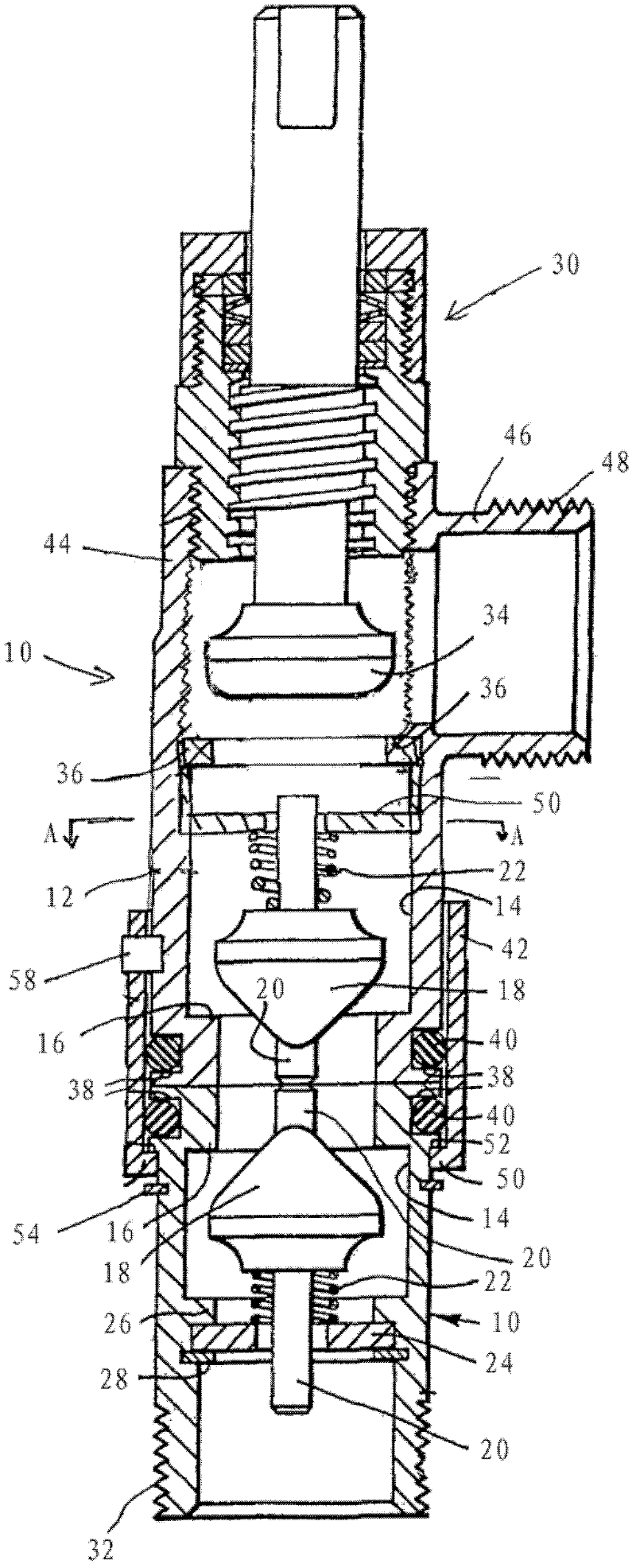
[0015] with reference to the attached figure 1 , the valve assembly includes two elongate valves 10 opposite to each other in length relationship. Each valve 10 comprises a tubular housing 12 in which a passage 14 is defined. The channel 14 of each valve has an inner peripheral valve seat 16 at one end, ie the end to be connected to another valve 10 , against which a movable valve member 18 is resiliently biased by a return spring 22 .

[0016] The valve member 18 of each valve is a poppet valve which is conical and may be made of rubber or other suitable synthetic plastic material. Each valve member 18 has a spigot device 20 at the center, with a part of the spigot device 20 protruding outwardly from said one end to extend beyond the adjoining end of the housing 12 under the influence of a corresponding return spring 22 . Each return spring comprises a helical compression spring 22 within a respective passage acting between a respective valve member 18 and a spring seat.

...


PUM


Abstract

A valve assembly comprising mutually opposed first and second valves (10), each of which comprises a casing (12) in which a through passage (14) is defined, the through passages having, at contiguous ends, internally circumferential valve seats (16) against which respective movable valve members (18) are biased, the respective valve members of the first and second valves engaging one another when the first and second valves are brought together to urge the valve members away from their respective seats to open the first and second valves, a coupling member being provided for holding the first and second valves together wherein means are provided for limiting the travel of the valve member of at least one of the first and second valves away from its valve seat to prevent the valve member of the other of the first and second valves from engaging its valve seat when the first and second valves are together, thus preventing said other of the first and second valves from closing due to the flow of fluid through the valve assembly.

Description

technical field [0001] The present invention relates to a valve assembly for use with, for example, a radiator or other liquid holding container or reservoir (hereinafter referred to simply as "reservoir" in the specification and claims) that is integrated of or to be integrated into tubular liquid systems. Background technique [0002] WO 91 / 09248 discloses a two-part radiator valve assembly for shutting off the water supply to enable the radiator to be removed. The valve assembly has two mutually opposed valves, each of the two mutually opposed valves includes a housing defining a passageway therein having an inner peripheral valve seat at an adjoining end, each The movable conical valve members are spring-biased against the inner peripheral valve seats via respective closure springs, and when the valves are brought together, the valve members engage each other to urge the valve members away from their respective Seat to open the valve. A bayonet sleeve extending betwee...

Claims


Application Information

Patent Timeline
Patent Type & Authority Applications(China)
IPC IPC(8): F16L37/32
CPCF16L37/32F16K27/02F16L37/107Y10T137/7838F16K17/065F16K39/045F16L29/007
Inventor 亚历山大.欧文
Owner 亚历山大.欧文
Features
  • R&D
  • Intellectual Property
  • Life Sciences
  • Materials
  • Tech Scout
  • Unparalleled Data Quality
  • Higher Quality Content
  • 60% Fewer Hallucinations
Learn More