Automatic press-riveting device for collecting element

An automatic and mounting seat technology, applied in the field of pressure riveting devices, can solve the problems of scratching the upper side of the pressure riveting point, etc., and achieve the effect of easy operation and high pressure riveting efficiency

Active Publication Date: 2012-04-18
中国航天科工集团第二研究院二十三所
View PDF7 Cites 10 Cited by
  • Summary
  • Abstract
  • Description
  • Claims
  • Application Information

AI Technical Summary

Problems solved by technology

[0004] The purpose of the present invention is to provide an automatic riveting device for collecting elements, which solves the problem of scratching the upper side of the riveting point during the circumferential riveting and riveting process of non-cylindrical workpieces

Method used


Image

  • Automatic press-riveting device for collecting element
  • Automatic press-riveting device for collecting element
  • Automatic press-riveting device for collecting element

Examples


Embodiment Construction

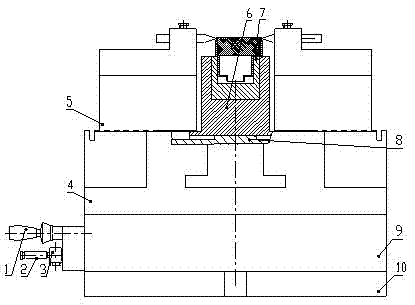
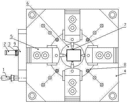
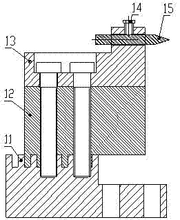
[0015] An automatic pressure riveting device for collecting elements, comprising: a pneumatic mechanism 9, a check valve 2, a switching handle 1, an air pressure gauge 3, a fixing plate 4, and also includes: a pressure riveting mechanism 5, a fixing seat 6, an adapter seat 7, an installation Seat 8, base 10; wherein, the riveting mechanism 5 includes: locking screw 14, carrier block 13, T-shaped slider 11, claw 12, thimble 15.

[0016] The base 10, the pneumatic mechanism 9 and the fixed plate 4 are all square in cross-section with the same cross-sectional size. The center of the base 10 has a threaded hole, the center of the pneumatic mechanism 9 has a through hole, and the center of the fixed plate 4 has a through hole. The base 10 is fixed on the horizontal platform, the pneumatic mechanism 9 is placed on the base 10 and fixed with screws, and the fixing plate 4 is placed on the pneumatic mechanism 9 and fixed with screws. There are four slide rails with a T-shaped section...


PUM


Abstract

The invention discloses an automatic press-riveting device for a collecting element. The automatic press-riveting device comprises a pneumatic mechanism (9), a check valve (2), a switching handle (1), an air pressure meter (3), a fixing plate (4), a press-riveting mechanism (5), a fixing base (6), a switching base (7), an installation base (8) and a base, wherein T-shaped slide blocks (11) at the lower end of the press-riveting mechanism (5) are arranged in four T-shaped slide rails of the fixing plate (4) respectively. In the working process of the automatic press-riveting device, the T-shaped slide blocks (11) are used for driving a claw (12), a carrier block (13) and a thimble (15) to move towards the axle center of the automatic press-riveting device under the pushing action of a cylinder to finish the press-riveting action; the switching handle (1) is switched to an initial position to finish the quitting action; and after press-riveting work is finished, press-riveted collecting elements are taken down. Due to the adoption of the automatic press-riveting device, press-riveting work of collecting units of various profiles can be finished; the press-riveting point depth and the press-riveting position can be adjusted freely; and the automatic press-riveting device is easy and convenient to operate, and has high press-riveting efficiency.

Description

technical field [0001] The invention relates to a riveting device, in particular to an automatic riveting device for collecting elements. Background technique [0002] The collecting element is formed by the socket of the medium sleeve and the medium block. The shape of the media sleeve is round, square or oval. In order to prevent the dielectric block from falling off from the dielectric sleeve, crimping points of a certain depth are often used to solve the problem of the dielectric block falling off around the collecting element. [0003] Patent application CN200710139328.1 discloses a circumferential riveting mechanism, which includes: cylinder, cylinder mounting seat, guide sleeve, guide shaft, fixed plate, tapered orifice plate, thimble, riveting block, spring, simple joint and bolt . The cylinder drives the thimble to move toward the center through the guide shaft to complete the riveting action. Although this mechanism can be used for riveting of cylindrical circu...

Claims


Application Information

Patent Timeline
Patent Type & Authority Applications(China)
IPC IPC(8): B21D39/00
Inventor 崔宪莉付纳新
Owner 中国航天科工集团第二研究院二十三所
Why Eureka
Try Eureka