Rotating cup bearing shell milling device for lathe

A bearing shell and lathe technology, applied to the milling device, positioning device, support, etc. that can be installed on the machine tool, can solve the problems of insufficient milling machine and no milling machine, and achieve the goal of improving processing efficiency, improving work efficiency and expanding the scope of use Effect

Inactive Publication Date: 2012-04-18
JINZHONG RENHE TEXTILE MACHINERY BEARING
View PDF4 Cites 46 Cited by
  • Summary
  • Abstract
  • Description
  • Claims
  • Application Information

AI Technical Summary

Problems solved by technology

[0003] The invention provides a milling device for the rotor cup bearing shell of a lathe, which solves the problem of using an ordinary lathe instead of a millin

Method used


Image

  • Rotating cup bearing shell milling device for lathe
  • Rotating cup bearing shell milling device for lathe
  • Rotating cup bearing shell milling device for lathe

Examples


Embodiment Construction

[0014] The milling device for the rotor cup bearing shell of the lathe according to the present invention will be described in detail below in conjunction with the accompanying drawings.

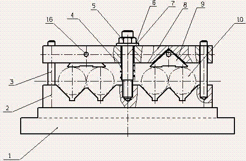
[0015] attached figure 1 The front view of the Doka clamp, the main part of the clamp shown in the figure is composed of a bottom plate 1, a V-shaped iron 2 and a frame-type pressure plate 8, wherein the V-shaped iron 2 is fixed on both sides of the bottom plate 1, and the V-shaped iron 2 is fixed on both sides There are several V-shaped grooves on the top, and each V-shaped groove is coaxially arranged with the V-shaped groove on the opposite side, and a workpiece is placed on each pair of V-shaped grooves. There are fixed screw holes in the middle of the V-shaped iron 2 on both sides, and fixed holes are formed at the corresponding positions of the longitudinal plates on both sides of the frame-type pressure plate 8, and the hold-down bolt 7 connects the frame-type pressure plate 8 a...


PUM


Abstract

The invention relates to a rotating cup bearing shell milling device for a lathe. The device comprises a main moving part and an auxiliary moving part, wherein the main moving part comprises a cutter rod and a cutter disc; and the auxiliary moving part is a multi-clamp fixture. The common lathe can be used for milling operation when the main moving part and the auxiliary moving part consisting of the multi-clamp fixture are combined and arranged on the lathe, so that the application range of the lathe is expanded, and work efficiency is improved; and a plurality of pieces of V-shaped iron are arranged on a bottom plate and matched with an upper part frame pressing plate structure, so that a plurality of workpieces can be fixed in the fixture at one time, and machining efficiency is improved exponentially.

Description

technical field [0001] The invention relates to a milling device for a lathe, which can expand the use range of the lathe and solve the problem of lack of milling machines. Background technique [0002] In the process of industrial production, it is often necessary to process sleeve parts in batches. Usually, a small processing enterprise has an annual output of tens of thousands or hundreds of thousands of individual parts that need to be processed, such as small bearing sleeves, etc. The outer surface of such parts is usually uniform. There are often several small planes on the side that need to be milled. The method of the prior art is to clamp the workpiece with a three-jaw and one indexing head, and mill it individually on a vertical milling machine. The production efficiency is extremely low and the processing cost is high, which is difficult to meet the needs. . If the number of milling machines is increased, due to the single application of milling machines, when th...

Claims


Application Information

Patent Timeline
IPC IPC(8): B23C7/02B23Q3/06
Inventor 张艳陈彩金韩冰张福生张武奎
Owner JINZHONG RENHE TEXTILE MACHINERY BEARING
Why Eureka
Try Eureka