Treatment process of injecting product in mold

An in-mold injection molding and processing technology, applied in the field of surface treatment, can solve the problems of inability to process sharp and angular structures, weak three-dimensional effect, low efficiency, etc., to ensure the pattern and aesthetics, product beauty, and enhance competitiveness. Effect

Inactive Publication Date: 2012-04-18
GUANGDONG JANUS SMART GRP CO LTD
View PDF6 Cites 20 Cited by
  • Summary
  • Abstract
  • Description
  • Claims
  • Application Information

AI Technical Summary

Problems solved by technology

Although the above two treatment processes can achieve a certain degree of three-dimensional effect, the three-dimensional effect is not strong, and process 1 can only process some smooth structures in the process of mold processing, but it cannot process sharp and angular structures, which has obvious advantages. limitation
The output of process 2 is low, it is not suitable for mass production, and the efficiency is low

Method used


Image

  • Treatment process of injecting product in mold
  • Treatment process of injecting product in mold

Examples


Embodiment 1

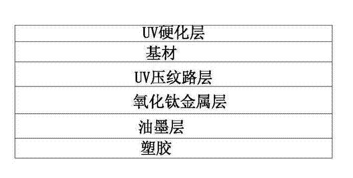
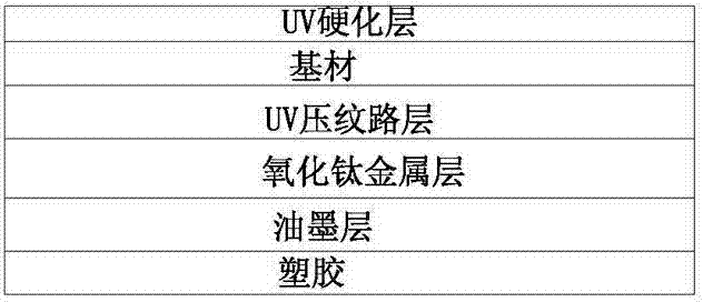
[0024] Example 1: (1) A PET sheet with a thickness of 0.1mm is selected as the substrate, and a UV topcoat is coated on one of the surfaces of the substrate. When the UV topcoat is applied, the temperature is 17°C and the relative humidity of the air is 55%, and then place the substrate in a curing oven for curing, so that the surface of the substrate is hardened to form a UV hardened layer, and the thickness of the UV hardened layer is 3 um. (2) Coat the UV topcoat on the other surface of the substrate, that is, the symmetrical surface of the UV hardened layer, and then die-cast textures on the UV topcoat. The pressure value during die-casting is 10000 Pa, and then the substrate Curing is performed to form a UV pattern layer on the surface of the substrate, and the thickness of the UV pattern layer is 3 um. (3) Vacuum sputtering is performed on the UV pattern layer, the target material is titanium oxide, so that a semi-transparent titanium oxide metal layer is formed on the UV...

Embodiment 2

[0025] Example 2: (1) A PET sheet with a thickness of 0.125mm is selected as the substrate, and a UV topcoat is coated on one of the surfaces of the substrate. When the UV topcoat is applied, the temperature is 20°C, and the relative humidity of the air is 60%, and then put the substrate in a curing oven for curing, so that the surface of the substrate is hardened to form a UV hardened layer, and the thickness of the UV hardened layer is 3.5 um. (2) Coat the UV topcoat on the other surface of the substrate, that is, the symmetrical surface of the UV hardened layer, and then die-cast textures on the UV topcoat. The pressure value during die-casting is 10000 Pa, and then the substrate Curing is performed to form a UV pattern layer on the surface of the substrate, and the thickness of the UV pattern layer is 3.5 um. (3) Vacuum sputtering is performed on the UV pattern layer, the target material is titanium oxide, so that a semi-transparent titanium oxide metal layer is formed on t...


PUM

PropertyMeasurementUnit
thicknessaaaaaaaaaa
thicknessaaaaaaaaaa
thicknessaaaaaaaaaa

Abstract

The invention discloses a treatment process of injecting a product in a mold, which comprises the following steps: (1) coating UV finish on one surface of a base material, curing to form a UV hardened layer; (2) coating the UV finish on the other surface of the base material, performing die casting on the UV finish to obtain lines, curing the base material in a curing furnace to form a UV line layer; (3) performing vacuum sputtering of a titanium oxide metal layer on the UV line layer, wherein the light transmittance of the titanium oxide metal layer is 75-80%; (4) printing an ink layer on the titanium oxide metal layer; (5) punching the base material with the printed ink layer to form a sheet material; (6) putting the punched sheet material in a corresponding injection mold to perform injection molding so as to obtain a finished product. The product processed by the treatment process of injecting a product in a mold of the invention has diamond cutting effect with high angularity and high stereoscopic impression, has high wear resistance, and is applicable to mobile phones, panel personal computers, and products with other structures.

Description

Technical field [0001] The invention relates to the technical field of surface treatment, in particular to a treatment process for in-mold injection products. Background technique [0002] Consumer electronic products such as mobile phones and tablet computers have become more and more popular. On the basis of increasingly powerful functions, the texture of the shell and the three-dimensional sense of the pattern have become more and more indicators of consumer choice. At present, the three-dimensional effect of the product plastic shell mainly includes the following two processing techniques. Process 1. After the lines are injected through the mold. Process 2. After engraving the desired pattern on the transparent material, coating or vacuum sputtering on the pattern will make the product produce a three-dimensional pattern effect. Although the above two treatment processes can achieve a certain degree of three-dimensional effect, the three-dimensional effect is not strong, an...

Claims


Application Information

Patent Timeline
Patent Type & Authority Applications(China)
IPC IPC(8): B29C45/17
Inventor 郭远军蒋小龙
Owner GUANGDONG JANUS SMART GRP CO LTD
Why Eureka
Try Eureka