
Horizontal goniometer for guide beam

A technology of level measuring instrument and guide beam, applied in height/level measurement, measuring device, measuring inclination, etc., can solve the problem of low adjustment accuracy

Inactive Publication Date: 2012-04-18
HEILONGJIANG JIANLONG IRON & STEEL
View PDF0 Cites 1 Cited by
  • Summary
  • Abstract
  • Description
  • Claims
  • Application Information

AI Technical Summary

Problems solved by technology

[0003] The purpose of the present invention is to provide a guide beam level measuring instrument to solve the problem of low adjustment accuracy in the detection of the height and level of the guide beam by naked eyes

Method used


Image

  • Horizontal goniometer for guide beam
  • Horizontal goniometer for guide beam

Examples


specific Embodiment approach 1

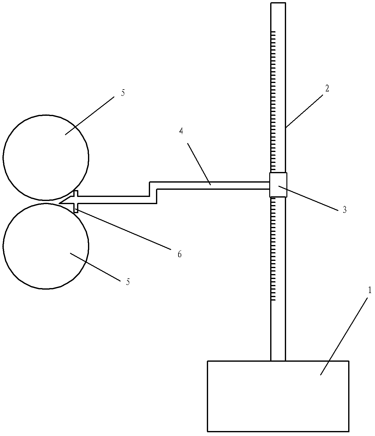
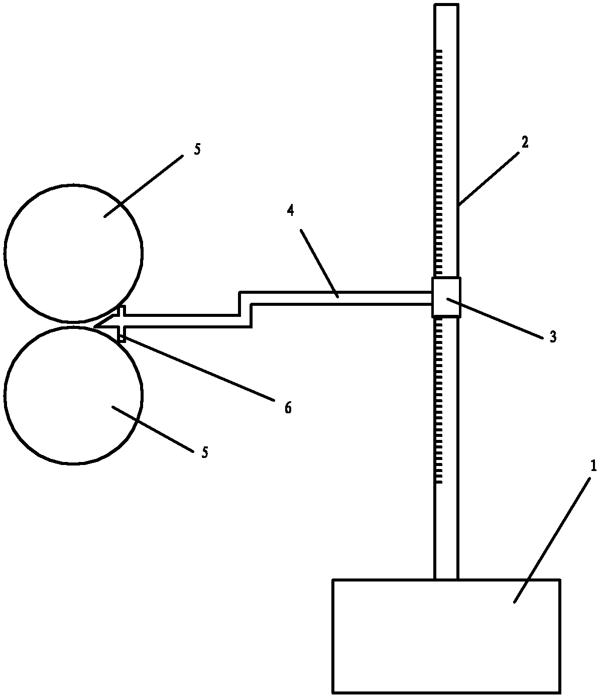
[0006] Specific implementation mode one: the following combination figure 1 This embodiment will be specifically described. This embodiment includes a base 1, a height gauge 2, a vernier 3 and a probe 4. The height gauge 2 arranged in the vertical direction is fixed on the base 1, and the vernier 3 that can slide and position along the body of the height gauge 2 is set On the body of the height gauge 2, one end of the probe 4 is fixed on the vernier 3, and the length direction of the probe 4 is arranged horizontally. The base 1, the height gauge 2, and the vernier scale 3 can select existing height micrometers.

specific Embodiment approach 2

[0007] Specific implementation mode two: the following combination figure 1 This embodiment will be specifically described. The difference between this embodiment and the first embodiment is that it also includes a positioning rod 6, which is fixed on the other end of the probe 4, and the distance between the ends of the positioning rod 6 and the probe 4 is equal. Because the guide beam 5 is a cylinder, when the probe 4 is stretched to the junction of the two guide beams 5, the positioning rod 6 is used to push against the cylindrical surface of a guide beam 5 respectively, which can ensure that the probe 4 is connected to the two guide beams 5. The distance between the guide beams 5 is equal.


PUM


Abstract

The invention relates to a horizontal goniometer for a guide beam, and particularly relates to a detection instrument for adjusting the height and levelness of the guide beam on a rolling mill. The horizontal goniometer solves the problem that the adjustment accuracy is low when the height and levelness of the guide beam are detected through visual inspection, and is used for adjusting the height and levelness of the guide beam on the rolling mill. The horizontal goniometer comprises a base, a height gauge, a vernier scale and a probe, wherein the height gauge vertically arranged is fixed on the base, the vernier scale capable of slipping and positioning along the body of the height gauge is sleeved on the body of the height gauge, one end of the probe is fixed on the vernier scale, and the length direction of the probe is horizontal.

Description

technical field [0001] The invention relates to a detection instrument used for adjusting the height and levelness of a guide beam on a rolling mill. Background technique [0002] The guide beam is an important part of the rolling mill, mainly used to support and adjust the guide installed on it. At present, there is no special detection instrument to detect the height and level of the guide beam of the rolling mill. Most of them are adjusted by naked eyes, which leads to low adjustment accuracy of the guide beam and brings damage to production and equipment. Contents of the invention [0003] The purpose of the present invention is to provide a guide beam level measuring instrument to solve the problem of low adjustment accuracy in detecting the height and levelness of the guide beam by naked eyes. It includes a base 1, a height gauge 2, a vernier 3 and a probe 4. The height gauge 2 set in the vertical direction is fixed on the base 1, and the vernier 3 that can slide an...

Claims


Application Information

Patent Timeline
IPC IPC(8): G01C9/00G01C5/00
Inventor 翟长宏戴诗浩赵永明
Owner HEILONGJIANG JIANLONG IRON & STEEL
Learn More