Orifice-plate-type air duct structure of volatile organic compound detection system

A volatile organic compound and detection system technology, which is applied in the direction of sampling devices, etc., can solve the problems of large detection error, affecting detection accuracy, and many adsorbents, and achieve the effects of reducing detection error, improving detection accuracy, and increasing flow rate

Inactive Publication Date: 2012-04-18
DONGGUAN CITY SIMPLEWELL TECH +1
View PDF6 Cites 2 Cited by
  • Summary
  • Abstract
  • Description
  • Claims
  • Application Information

AI Technical Summary

Problems solved by technology

[0002] The volatile organic compound detection system is used to detect products containing volatile organic compounds to detect whether the volatile organic content of the product meets the requirements of relevant standards. During the detection process, the inner wall of the test chamber absorbs volatile organic compounds to form adsorbents. Moreover, there are dead corners on the inner wall of the test chamber, there are dead corners, and organic matter remains. When sampling and analyzing the content of volatile organic compounds, the samples obtained from the sampling port of the volatile organic compound detection system are used for detection. A large number of volatile organic compounds, resulting in the detection value obtained from the sample is lower than the actual value of the volatile organic compounds in the test chamber, the detection error is large, and it cannot effectively meet the high-precision detection needs. In order to strengthen the flow of gas in the test chamber, in the test A fan is installed in the chamber for stirring, but due to the requirement of the wind speed in the test chamber, the internal circulating air volume cannot be too large, so there are many adsorbents on the inner wall of the test chamber, which affects the detection accuracy

Method used


Image

  • Orifice-plate-type air duct structure of volatile organic compound detection system
  • Orifice-plate-type air duct structure of volatile organic compound detection system
  • Orifice-plate-type air duct structure of volatile organic compound detection system

Examples


Embodiment Construction

[0015] The following best embodiments of the orifice air duct structure of the volatile organic compound detection system of the present invention are not intended to limit the protection scope of the present invention.

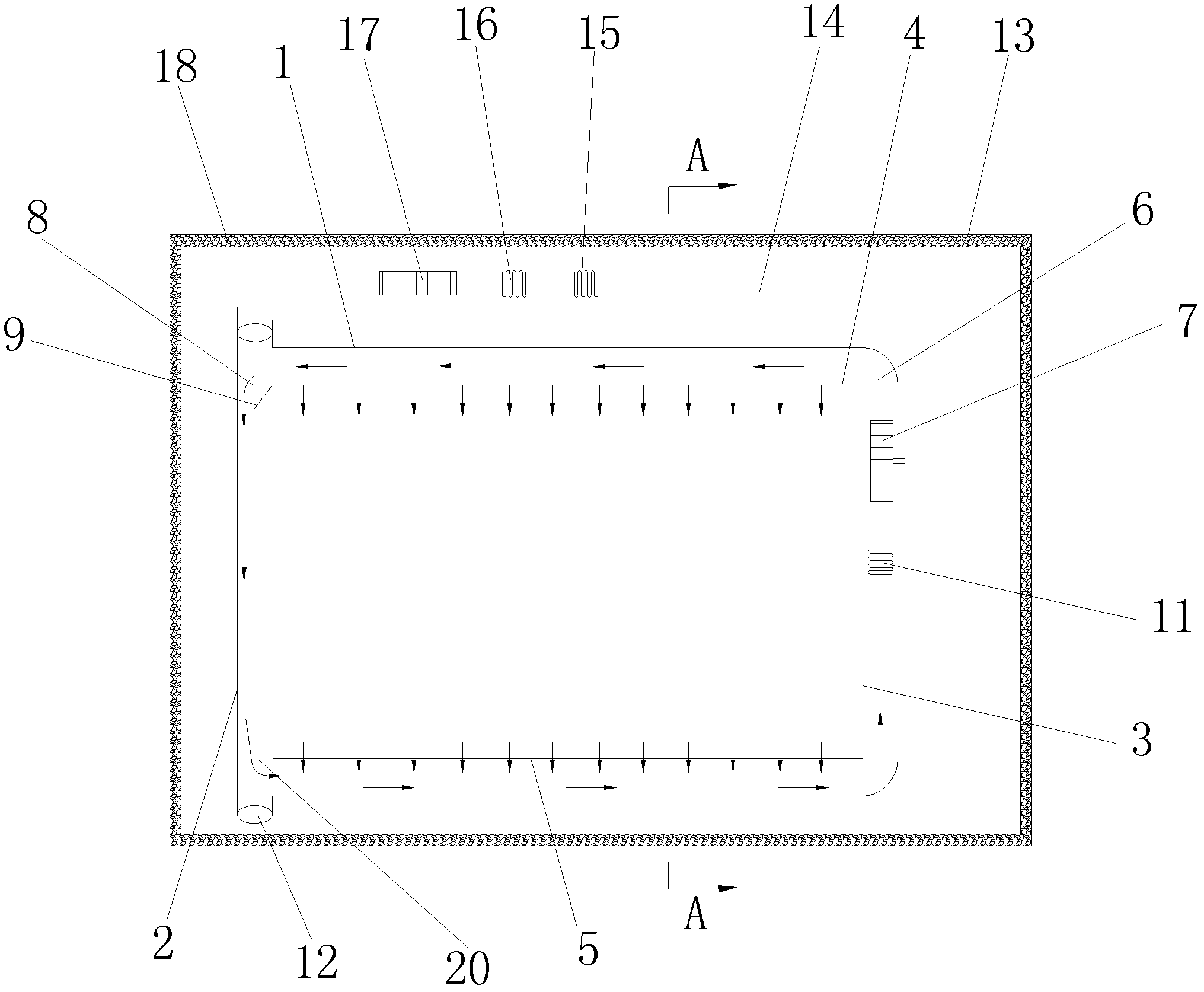
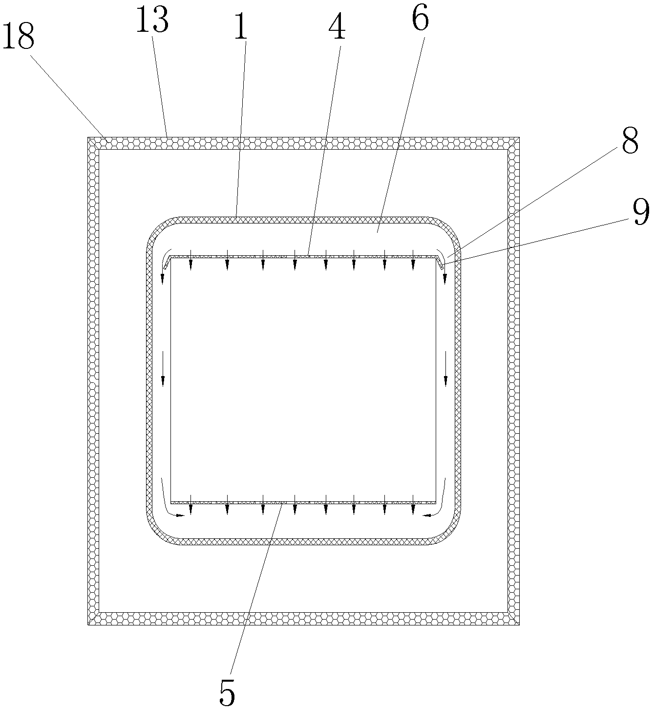
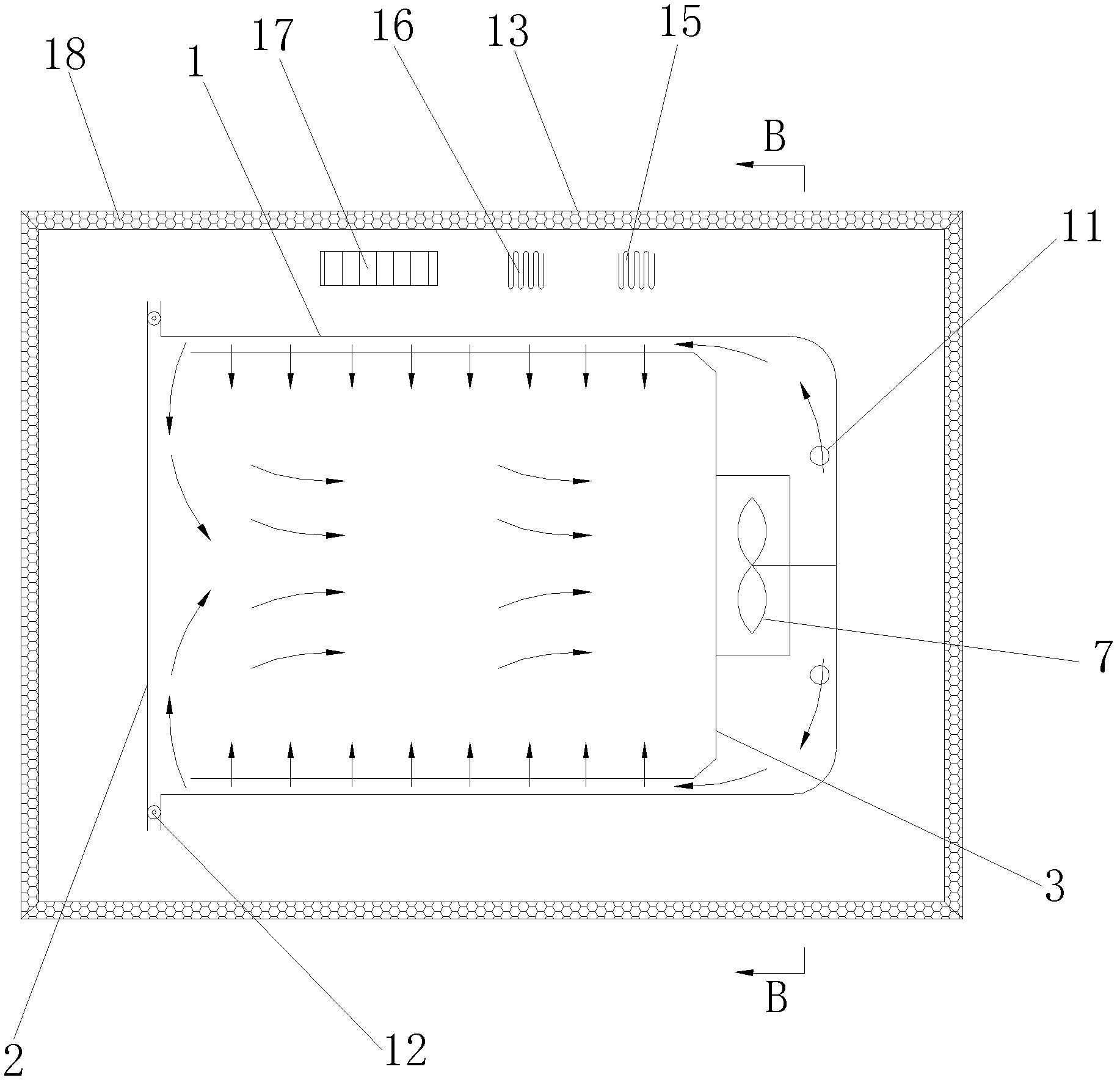
[0016] refer to figure 1 , figure 2 , providing an orifice-type air duct structure for a volatile organic compound detection system, including a test chamber 1, a test chamber door 2 connected to the test chamber 1, and an air duct plate 3 and an air duct plate are also installed in the test chamber 1 3 is equipped with an air outlet orifice 4, and the lower part of the air duct plate 3 is equipped with a return air orifice 5. The air duct 3, the air outlet orifice 4, and the return air orifice 5 form a first Air duct 6, the first air duct 6 is equipped with at least one test chamber circulation fan 7, the structure of the test chamber circulation fan 7 is a fan blade or a wind wheel, the air outlet orifice plate 4 and the inner wall of the test chamber 1 a...


PUM


Abstract

The invention discloses an orifice-plate-type air duct structure of a volatile organic compound detection system. The structure disclosed by the invention comprises a test bin and a test bin gate connected with the test bin, wherein the test bin is also internally provided with an air duct plate; the upper part of the air duct plate is provided with an air outlet orifice plate, and the lower partof the air duct plate is provided with an air return orifice plate; the air duct plate, the air outlet orifice plate, the air return orifice plate and the inner wall of the test bin form a first air duct; the first air duct is internally provided with at least one test bin circulating fan; the air outlet orifice plate, the inner wall of the test bin and the inner wall of the test bin gate are provided with air outlets and air return ports; and the air outlet orifice plate is provided with a right-angled, inclined or circular-arc-shaped air deflector. In the test bin, airflow blown down along the inner wall of the test bin is formed, thus adsorbed substances on the inner wall of the test bin are blown down so as to be continuously circulated in the test bin, so that the detected detection value of a sample obtained during sampling is more approximate to the actual value of the volatile organic compound in the test bin, the detection error is greatly reduced, and the detection precisionis improved.

Description

technical field [0001] The invention relates to a volatile organic compound detection system, and more specifically relates to an orifice-type air duct structure of the volatile organic compound detection system. technical background [0002] The volatile organic compound detection system is used to detect products containing volatile organic compounds to detect whether the volatile organic content of the product meets the requirements of relevant standards. During the detection process, the inner wall of the test chamber absorbs volatile organic compounds to form adsorbents. Moreover, there are dead corners on the inner wall of the test chamber, there are dead corners, and organic matter remains. When sampling and analyzing the content of volatile organic compounds, the samples obtained from the sampling port of the volatile organic compound detection system are used for detection. A large number of volatile organic compounds, resulting in the detection value obtained from ...

Claims


Application Information

Patent Timeline
Patent Type & Authority Applications(China)
IPC IPC(8): G01N1/22
Inventor 夏可瑜卢志刚王华
Owner DONGGUAN CITY SIMPLEWELL TECH
Why Eureka
Try Eureka