Energy recovery in hot strip mills by converting the cooling heat of the continuous casting plant and the residual heat of slabs and coils into electrical energy or otherwise utilizing the captured process heat

A technology of casting equipment and slabs, applied in mechanical equipment, sustainable manufacturing/processing, heat exchangers, etc., can solve problems such as heat loss

Inactive Publication Date: 2012-04-18
SMS GRP GMBH
View PDF9 Cites 25 Cited by
  • Summary
  • Abstract
  • Description
  • Claims
  • Application Information

AI Technical Summary

Problems solved by technology

Currently, this heat is lost unused to the environment (air and cooling water)

Method used


Image

  • Energy recovery in hot strip mills by converting the cooling heat of the continuous casting plant and the residual heat of slabs and coils into electrical energy or otherwise utilizing the captured process heat
  • Energy recovery in hot strip mills by converting the cooling heat of the continuous casting plant and the residual heat of slabs and coils into electrical energy or otherwise utilizing the captured process heat
  • Energy recovery in hot strip mills by converting the cooling heat of the continuous casting plant and the residual heat of slabs and coils into electrical energy or otherwise utilizing the captured process heat

Examples


Embodiment Construction

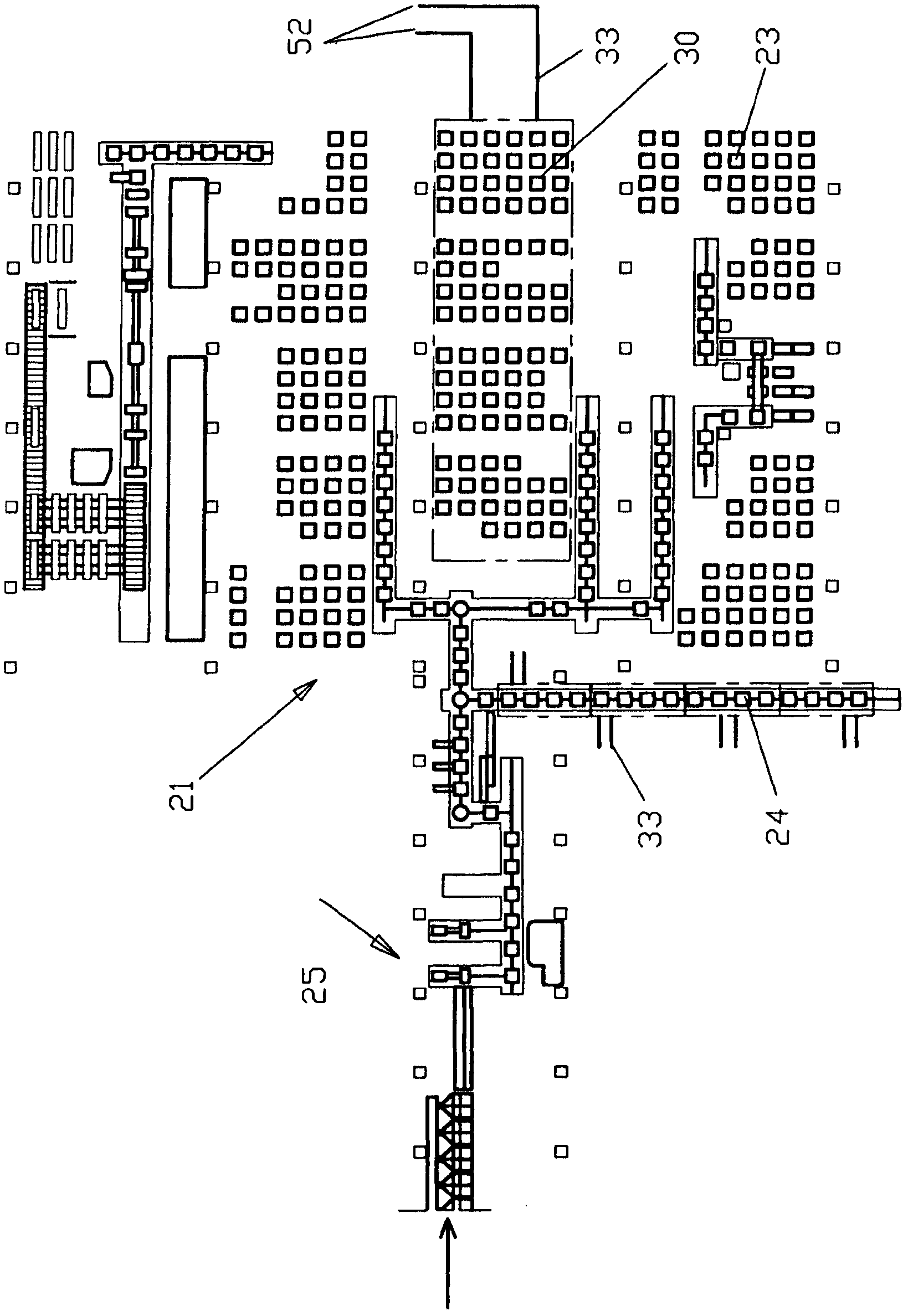
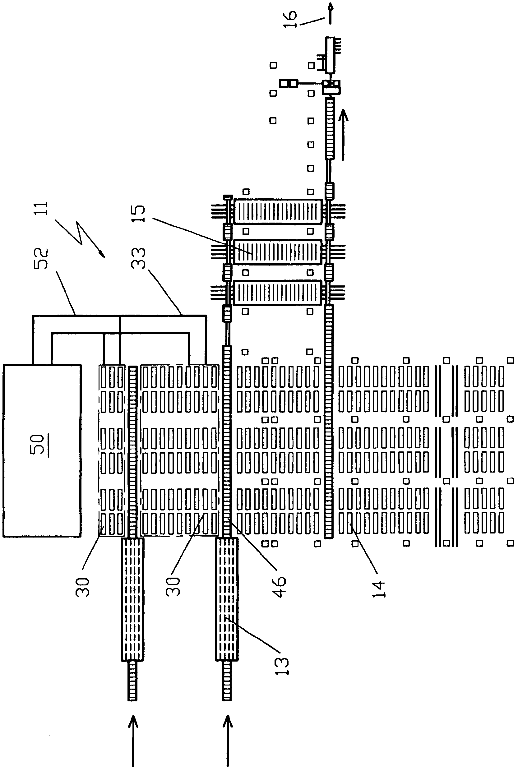
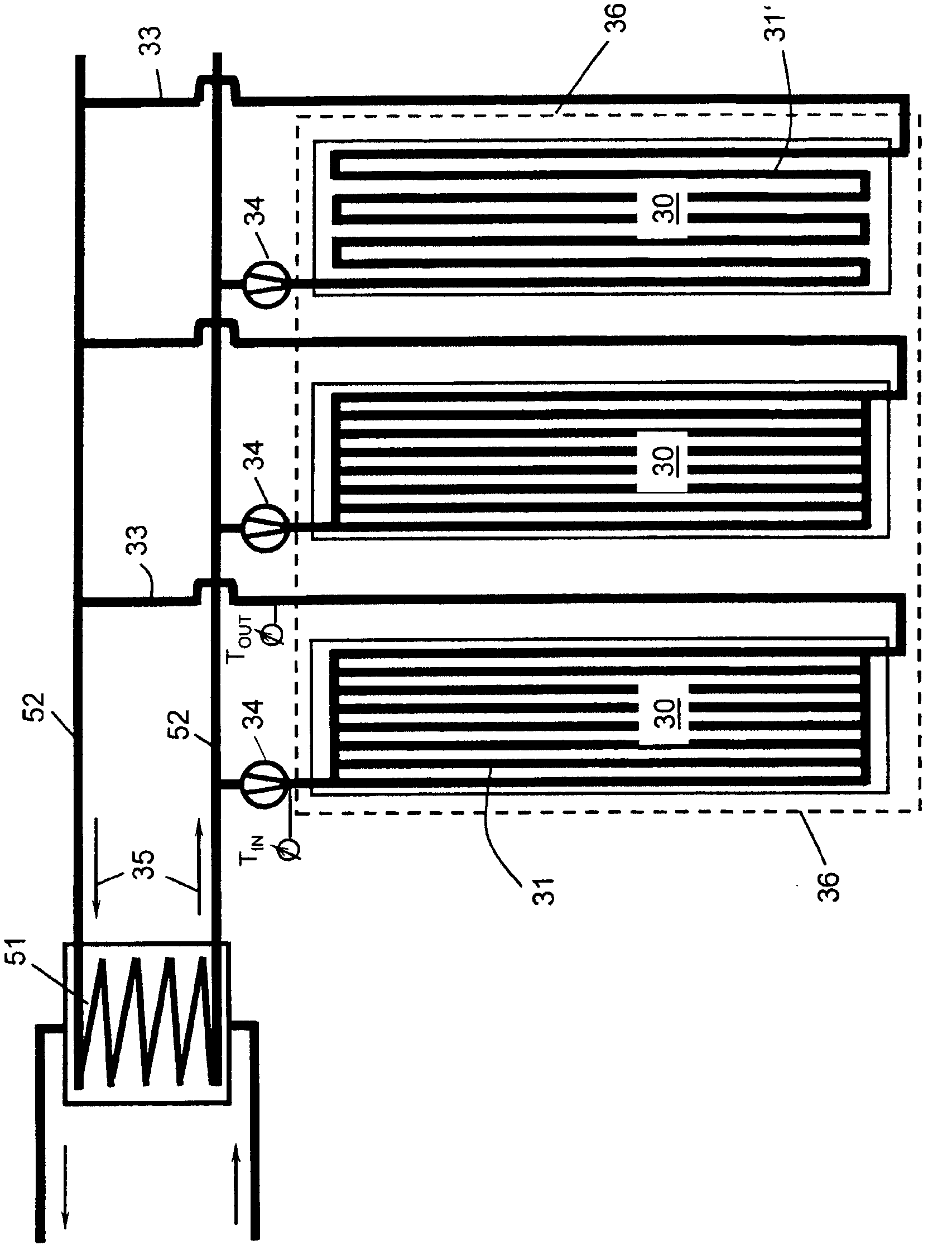
[0097] exist figure 1 , the coil warehouse 21 is shown in plan view. The coil produced by the winch 25 reaches its storage location via a coil-conveying line 24 (which can be configured, for example, with a heat exchanger cover or heat shield). According to the invention, these storage locations are partially configured as storage locations 30 with heat exchangers 31 (see Figure 8a and 8b ), leaving the rest as usual coil-storage locations 23 without heat exchangers. Depending on the still existing temperature and cooling progress of the coils, between the storage position 23 and the storage position 30 , a change of the coils takes place which is controlled by the process model. The heat carrier medium heated in the storage location 30 then reaches the power generation equipment (power generation equipment not shown) via the heat carrier-conveying pipeline 33 and the heat carrier-collecting pipeline 52, or can be transported to other internal or External heat users (e.g....


PUM


Abstract

In hot strip plants the residual heat of a part of the slabs after casting was hitherto utilized by either directly rolling the slabs or inserting the slabs into the furnace in a still warm or hot state. After casting, the remaining slabs usually cool down in an aerated hall and are stacked before being further conveyed. The same applies to the residual heat which is present after coiling in the coils which are often air-cooled in a coil storage. The cooling energy of the continuous casting plant also escapes into the environment without being utilized.; According to the invention said unutilized solidification and residual heat is converted into electrical energy by casting the slabs (10) in a continuous casting plant, conveying the slabs (10) or coils to the slab storage (12) or coil storage, removing heat therefrom in heat exchangers (31) during casting and / or during conveying, and / or placing the slabs for a short time or for several hours partially stacked on specifically prepared storage areas (30) which are designed with heat exchangers (31), wherein during the conveying period the heat of the cast strand or the slab (10) and / or during the storage period the residual heat of the slabs (10) or coils is transferred by means of heat conduction and heat radiation and convection via the heat exchangers (31) to a heat carrying medium, such as thermal oil,; thereby heating the heat carrying medium which is then removed via heat carrier transport ducts (33) for power generation and / or for direct utilization of the process heat in other heat consumers.

Description

technical field [0001] The invention relates to a method and a plant for recovering energy in continuous casting plants and hot strip rolling mills (Warmbandstrasse), especially in the production and processing of slabs (Bramme) to strip or coils, wherein The heat energy released when the billet (Gieβstrang) as well as the slab or coil cools is captured and utilized. Background technique [0002] When the steel is cooled from about 1570° C. (liquid state) to an intermediate temperature of about 1200° C., the steel is deprived of about 145 kWh / t of heat energy at the outflow from the continuous casting plant. Currently, this heat is lost unused to the environment (air and cooling water). [0003] In hot-strip installations, after casting, the residual heat of the slab has hitherto been utilized in that the slab is either directly rolled or fed warm or hot into the furnace. A lot of heating energy can thus be saved. A prerequisite for hot or direct use is the physical proxi...

Claims


Application Information

Patent Timeline
Patent Type & Authority Applications(China)
IPC IPC(8): B22D11/124B22D11/22F01K17/00F01K23/00
CPCF01K25/08B22D11/22B22D11/124F01K17/02B22D11/00F01K17/04Y02E20/14F01K13/02B22D11/14F28D21/0001Y02P80/15
Inventor P·苏多J·赛德尔H·格特纳A·斯塔夫诺
Owner SMS GRP GMBH
Why Eureka
Try Eureka