Cloth rolling shaft with hold-down groove

A technology of cloth winding shaft and fixing groove, which is applied in the field of cloth winding shaft with fixing groove, which can solve the problems that the cloth is not tight, the gauze cannot be fixed, and the gauze is easy to fall off, etc., and achieves the effect of simple structure

Inactive Publication Date: 2012-04-25
黄呈添
View PDF5 Cites 8 Cited by
  • Summary
  • Abstract
  • Description
  • Claims
  • Application Information

AI Technical Summary

Problems solved by technology

But this kind of cloth reel has the same disadvantages. There is no fixing groove on the surface of the cloth reel, so the gauze cannot be fixed, the gauze is easy to fall off, and the rolled out cloth is not tight.

Method used


Image

  • Cloth rolling shaft with hold-down groove
  • Cloth rolling shaft with hold-down groove
  • Cloth rolling shaft with hold-down groove

Examples


Embodiment Construction

[0019] The preferred embodiments of the present invention will be described in detail below in conjunction with the accompanying drawings, so that the advantages and features of the present invention can be more easily understood by those skilled in the art, so as to define the protection scope of the present invention more clearly.

[0020] The invention provides a cloth take-up shaft with a simple structure and a fixing groove.

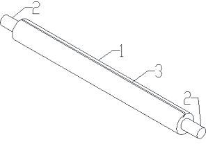
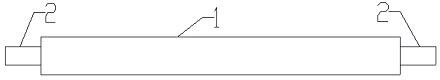
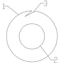
[0021] Such as figure 1 , figure 2 , image 3 As shown, a cloth rolling shaft with a fixing groove, the cloth rolling shaft includes a pipe body 1 and a rotating shaft 2, the pipe body 1 is provided with a fixing groove 3, the fixing groove 3 runs through the pipe body 1, and the rotating shaft 2 is arranged on Both ends of the tube body 1.

[0022] Such as figure 1 , image 3 As shown, the fixing groove 3 is arranged obliquely to the radial direction of the pipe body 1 , and the inclination direction of the fixing groove 3 is arranged along t...


PUM


Abstract

The invention discloses a cloth rolling shaft with a hold-down groove. The cloth rolling shaft comprises a pipe body and revolving shafts, wherein the pipe body is provided with the hold-down groove; the hold-down groove passes through the pipe body; the revolving shafts are arranged at the two ends of the pipe body; the hold-down groove is arranged obliquely in the radial direction of the pipe body; the inclination direction of the hold-down groove is formed along the rotating direction of the cloth rolling shaft; and the depth of the hold-down groove is equal to one third of the diameter of the pipe body. The cloth rolling shaft disclosed by the invention has the advantages of simple structure, prevention of gauze from sliding easily during cloth rolling due to the adoption of the hold-down groove, and the like.

Description

technical field [0001] The invention relates to a cloth winding shaft, more precisely a cloth winding shaft with a fixing groove. Background technique [0002] Cloth winding shafts are widely used in textile mills, but the surface of the cloth winding shafts in the prior art does not have a fixed groove, and the cloth winding action is completed only by the friction between the gauze and the cloth winding shaft. When the cloth winding shaft is working, The gauze is easy to move along the circumferential direction of the winding shaft, and the rolled cloth is not tight. [0003] Chinese invention patent ZL 02266692.3 discloses a hollow pipe body, which is provided with a slot extending in the axial direction on the periphery of the cloth rolling sleeve, and the inner side of the cloth rolling sleeve is provided with a plurality of inner protrusions parallel to the axial direction. The extended inner convex part allows the two ends of the cloth winding shaft sleeve to be inse...

Claims


Application Information

Patent Timeline
Patent Type & Authority Applications(China)
IPC IPC(8): B65H75/26
Inventor 黄呈添
Owner 黄呈添
Why Eureka
Try Eureka