Split guide beam type tunnel-passing bridge girder erecting machine

A bridge erecting machine and tunnel passing technology, which is applied in the field of structural improvement, can solve the problems of unable to complete the opening of the opening beam, high stability of the guide beam, and large cross-section of the rear outrigger

Active Publication Date: 2012-04-25
CHINA RAILWAY ENG MASCH RES & DESIGN INST CO LTD
View PDF9 Cites 15 Cited by
  • Summary
  • Abstract
  • Description
  • Claims
  • Application Information

AI Technical Summary

Problems solved by technology

[0015] The present invention mainly solves the problem that the auxiliary guide beam type bridge erecting machine and the walking type bridge erecting machine in the prior art have a large section of the rear legs, which cannot complete the beam erection at the opening, and the guide beam type fixed point lifting bridge erecting machine passes through the The combination of the beam transport vehicle can realize the construction of the beam at the tunnel entrance, but it usually requires a large dismantling to pass through the tunnel. The construction efficiency of the integrated machine for transport and frame is very low, and the guide beam requires high stability. Used together, it can realize zero distance, negative distance at the tunnel entrance and the split guide beam type tunnel bridge erecting machine for erecting beams in the tunnel.

Method used


Image

  • Split guide beam type tunnel-passing bridge girder erecting machine
  • Split guide beam type tunnel-passing bridge girder erecting machine
  • Split guide beam type tunnel-passing bridge girder erecting machine

Examples


Embodiment

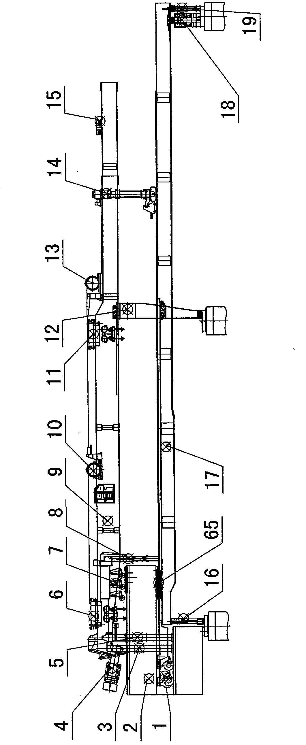
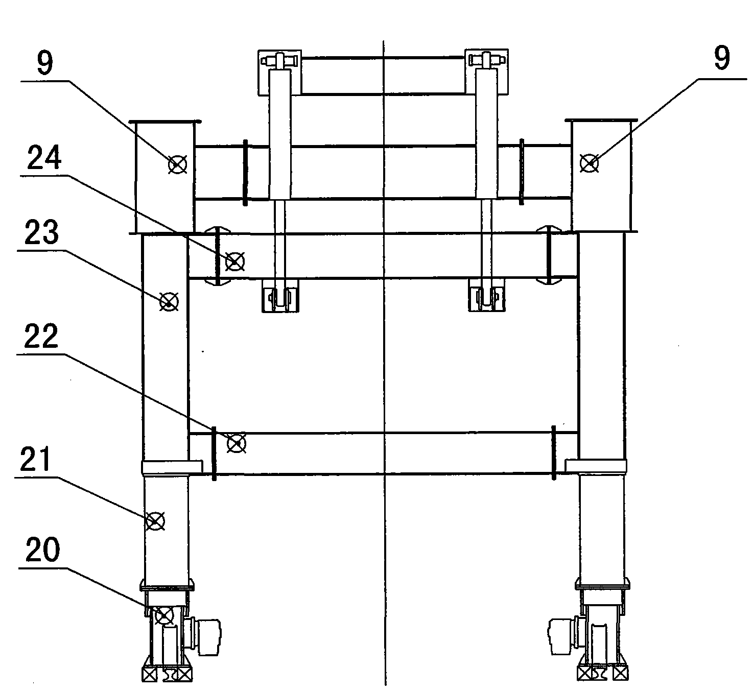
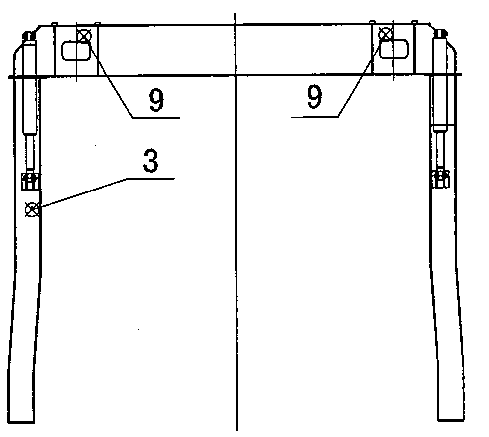
[0045] The split guide beam type tunnel bridge erecting machine includes a main beam and a lower guide beam arranged below the main beam. The lower guide beam is sequentially provided with front legs, middle legs and rear legs for supporting the lower guide beam. Outriggers; the main beam is sequentially provided with traction devices for pulling the front outriggers and middle outriggers to turn over, front support devices for supporting the main beam, and front lifting devices for lifting the box girder to be erected And the rear lifting device, the middle supporting device for supporting the main girder, the C-shaped outrigger for supporting the main girder and enabling the box girder to be erected to pass therethrough, and the rear supporting device for supporting the main girder. The C-shaped legs can pass through the tunnel by folding themselves. The main girder of the lower guide beam is a fish belly type, the rear end is a single main girder, and the front end is a dou...


PUM


Abstract

The invention relates to a bridge girder erecting machine, in particular to structural improvement on a split guide beam type tunnel-passing bridge girder erecting machine. The split guide beam type tunnel-passing bridge girder erecting machine comprises a girder and a lower guide beam, wherein the lower guide beam is arranged below the girder, a front leg, an intermediate leg and a rear leg which are used for supporting the lower guide beam are sequentially arranged on the lower guide beam, a traction device, a front support device, a front lifting device, a rear lifting device, an intermediate support device, a C-shaped leg and a rear support device are sequentially arranged on the girder, the traction device is used for drawing the front leg and the intermediate leg to turn over, the front support device is used for supporting the girder, the front lifting device and the rear lifting device are used for hoisting a box beam to be erected, the intermediate support device is used for supporting the girder, the C-shaped leg is used for supporting the girder and making the box beam to be erected pass through the girder, and the rear support device is used for supporting the girder. The split guide beam type tunnel-passing bridge girder erecting machine has the following advantages that zero-distance or minus-distance beam erecting at a tunnel portal or in a tunnel can be realized when the bridge girder erecting machine is used with a low-level beam transportation vehicle in a matching way, tunnel passing can be realized in a slight disassembly and assembly manner, and the legs of the guide beams at an initial hole and an end hole can be disassembled and assembled through a mechanism of the bridge erecting machine per se.

Description

technical field [0001] The invention relates to a bridge erecting machine, in particular to a structural improvement to the split guide beam type tunnel bridge erecting machine. Background technique [0002] In conventional large-tonnage concrete box girder transport equipment, beam transport vehicles are usually used in conjunction with the following types of bridge erecting machines. The height of the beam truck is generally about 3 meters. [0003] 1. Auxiliary guide beam bridge erecting machine [0004] As an auxiliary part of the bridge erecting machine, the guide beam only assists the bridge erecting machine to complete the hole-passing operation. The main girder has a tail suspension at the rear of the rear outrigger of the bridge erecting machine, and the position of taking the beam is at the rear of the rear outrigger. [0005] 2. Guide beam type fixed-point lifting bridge erecting machine [0006] The guide beam not only assists the bridge erecting machine to c...

Claims


Application Information

Patent Timeline
Patent Type & Authority Applications(China)
IPC IPC(8): E01D21/06
Inventor 张智莹王光欣李晓钢林承朝党春太尹卫陈家乐罗璞徐永冯强胡超
Owner CHINA RAILWAY ENG MASCH RES & DESIGN INST CO LTD
Why Eureka
Try Eureka