Construction method of preserved foundation bolt hole of equipment foundation

A technology for anchor bolts and equipment foundations, which is applied in the construction field where anchor bolt holes are reserved for equipment foundations. It can solve the problem of inability to meet the cross-section requirements of large lower openings and small upper openings, affecting the strength of anchor bolt holes, and templates that cannot be repeated Use and other issues to achieve the effect of reducing labor intensity, easy promotion, and reducing construction costs

Active Publication Date: 2014-03-26
CHINA FIRST METALLURGICAL GROUP
View PDF4 Cites 0 Cited by
  • Summary
  • Abstract
  • Description
  • Claims
  • Application Information

AI Technical Summary

Problems solved by technology

The steel corrugated pipe adopts a tool with a slot at one end and a handle at the other end. The slot is clamped to the steel bellows, and the steel corrugated pipe is peeled off layer by layer. The removal effect is not satisfactory; the plastic pipe is baked at high temperature to make it soft, and then Pulling out as a whole, the method sometimes causes the plastic pipe to break off, which directly affects the strength of the secondary grouting of the anchor bolt holes; the wooden formwork adopts a square pyramid-shaped wooden box structure with a large upper opening and a smaller lower opening, with small cross-section and deep depth. For deep holes, there will be various difficulties such as difficulty in force and limited space when dismantling
In order to improve the pull-out bearing capacity of bolts, a structure with the lower opening slightly larger than the upper opening is often adopted. Steel bellows and plastic pipes are standard materials with equal diameters, which cannot meet the requirements of a large lower opening and a small upper opening, and cannot be dismantled.
Namely: the anchor bolt hole is characterized by a long and narrow space with a large aspect ratio, so it brings great inconvenience to the demolition, and its formwork cannot be reused during the demolition process

Method used


Image

  • Construction method of preserved foundation bolt hole of equipment foundation
  • Construction method of preserved foundation bolt hole of equipment foundation
  • Construction method of preserved foundation bolt hole of equipment foundation

Examples


Embodiment Construction

[0026] In order to better understand the present invention, the technical solutions of the present invention will be further described below in conjunction with the embodiments and the accompanying drawings.

[0027] The construction method of the reserved anchor bolt hole of the equipment foundation provided by the present invention comprises the following steps:

[0028] The first step, assemble the mold:

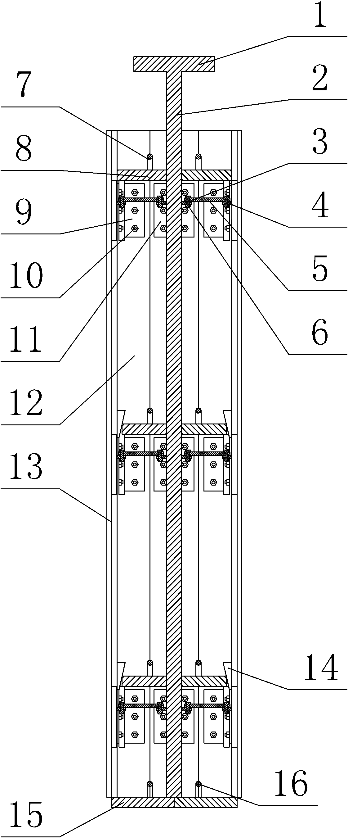
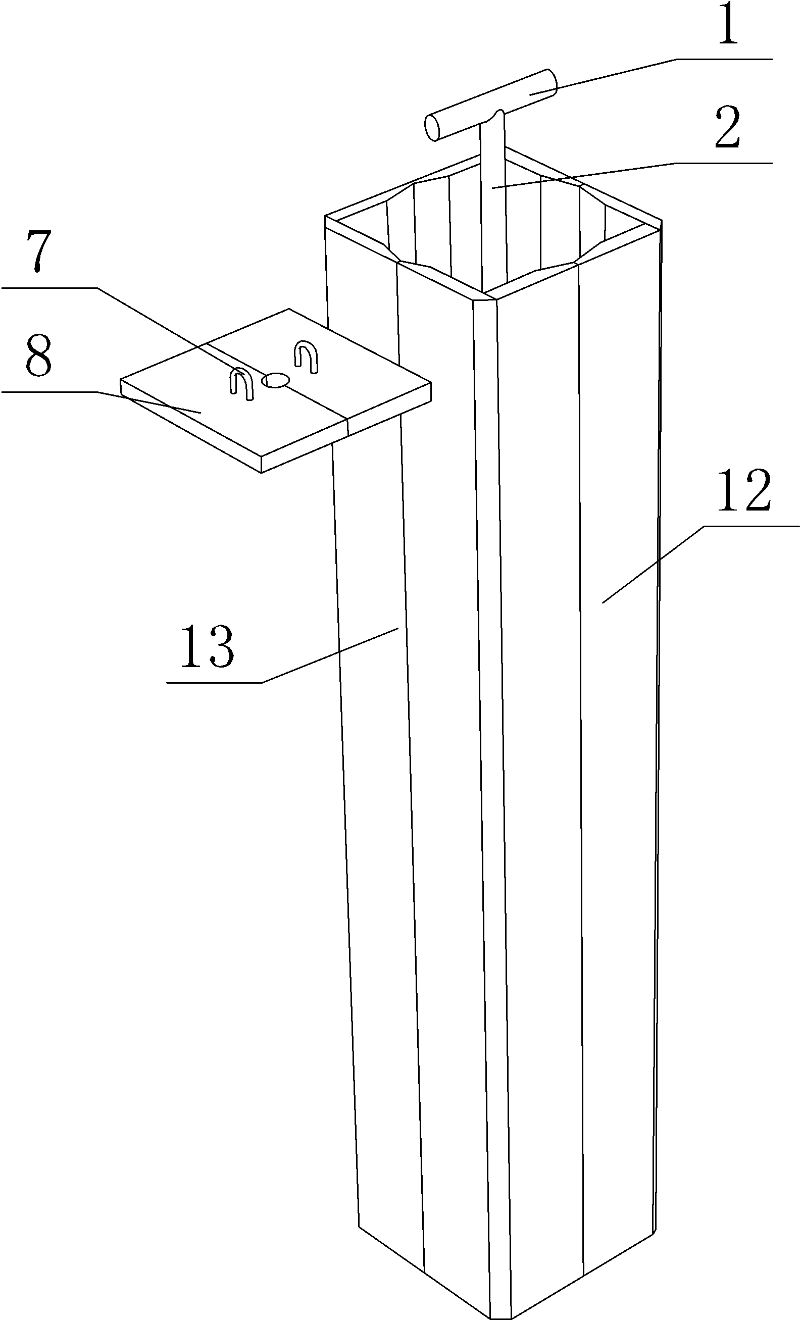
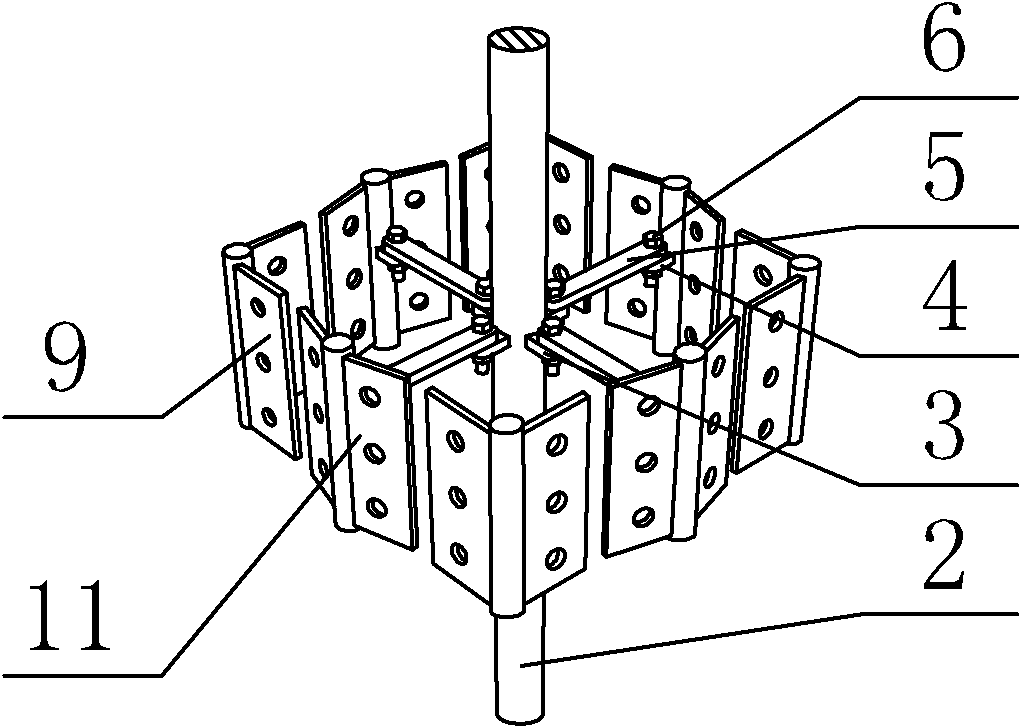
[0029] A reusable mold for the anchor bolt holes of the equipment foundation (its structure is as follows Figure 1 to Figure 5 As shown), it includes a central axis 2, 2-4 expansion and contraction devices, and 8 templates (the templates are rectangular, respectively the first template 12, the second template 13, the third template, the fourth template, the fifth template Templates, sixth templates, seventh templates, eighth templates), upper plate 8; each 2 templates are located on one side, and 8 templates form a square (square or rectangle); 2-4 expansion and contrac...


PUM


Abstract

The invention relates to a construction method of a preserved foundation bolt hole of an equipment foundation. The construction method is characterized by comprising the following steps of: 1, assembling a mould, wherein the mould comprises a center shaft, 2-4 spreading and contracting devices, 8 templates and an upper plate, every two templates are positioned on one side, the 8 templates are enclosed to form a square, the 2-4 spreading and contracting devices are positioned in a square cavity formed by enclosing the 8 templates, the lower end of the center shaft penetrates through the 2-4 spreading and contracting devices, a handle is welded on the upper end of the center shaft; 2, erecting the mould; 3, pouring concrete; 5, dismantling the mould, preserving a hole; and 5, cleaning the hole: galling the concrete surface around the hole by using an iron hook or steel brush, cleaning waste in the hole, and sealing the hole to obtain the preserved foundation bolt hole of the equipment foundation. The construction method is simple; and the used mould is simple in operation and high in template-dismantling speed, and can be repeatedly used.

Description

technical field [0001] The invention relates to a construction method for reserving anchor bolt holes for equipment foundations. Background technique [0002] In the construction of large-scale equipment foundation, the anchor bolt holes of the equipment need to be reserved on the concrete foundation. The reserved method generally adopts the method of supporting steel bellows, plastic pipe or supporting wooden formwork, etc., and removes it in time after the concrete solidifies. The steel corrugated pipe adopts a tool with a slot at one end and a handle at the other end. The slot is clamped to the steel bellows, and the steel corrugated pipe is peeled off layer by layer. The removal effect is not satisfactory; the plastic pipe is baked at high temperature to make it soft, and then Pulling out as a whole, the method sometimes causes the plastic pipe to break off, which directly affects the strength of the secondary grouting of the anchor bolt holes; the wooden formwork adopts...

Claims


Application Information

Patent Timeline
Patent Type & Authority Patents(China)
IPC IPC(8): E04G15/04E04G19/00E04G21/02
Inventor 王平夏春
Owner CHINA FIRST METALLURGICAL GROUP
Why Eureka
Try Eureka