Heat-exchange tube

A heat exchange tube and tube body technology, which is applied in heat exchange equipment, tubular elements, lighting and heating equipment, etc., can solve the problem of increased heat exchange area, achieve increased heat exchange area, improved heat transfer performance, and enhanced heat transfer The effect of the process

Inactive Publication Date: 2012-04-25
JIANGSU CUILONG PRECISION COPPER TUBE CORP
View PDF7 Cites 12 Cited by
  • Summary
  • Abstract
  • Description
  • Claims
  • Application Information

AI Technical Summary

Problems solved by technology

Not limited to the heat transfer tubes disclosed in these patents Since the secondary grooves are only formed at the ends of the fins, the increase in heat transfer area is very limited

Method used


Image

  • Heat-exchange tube
  • Heat-exchange tube
  • Heat-exchange tube

Examples


Embodiment 1

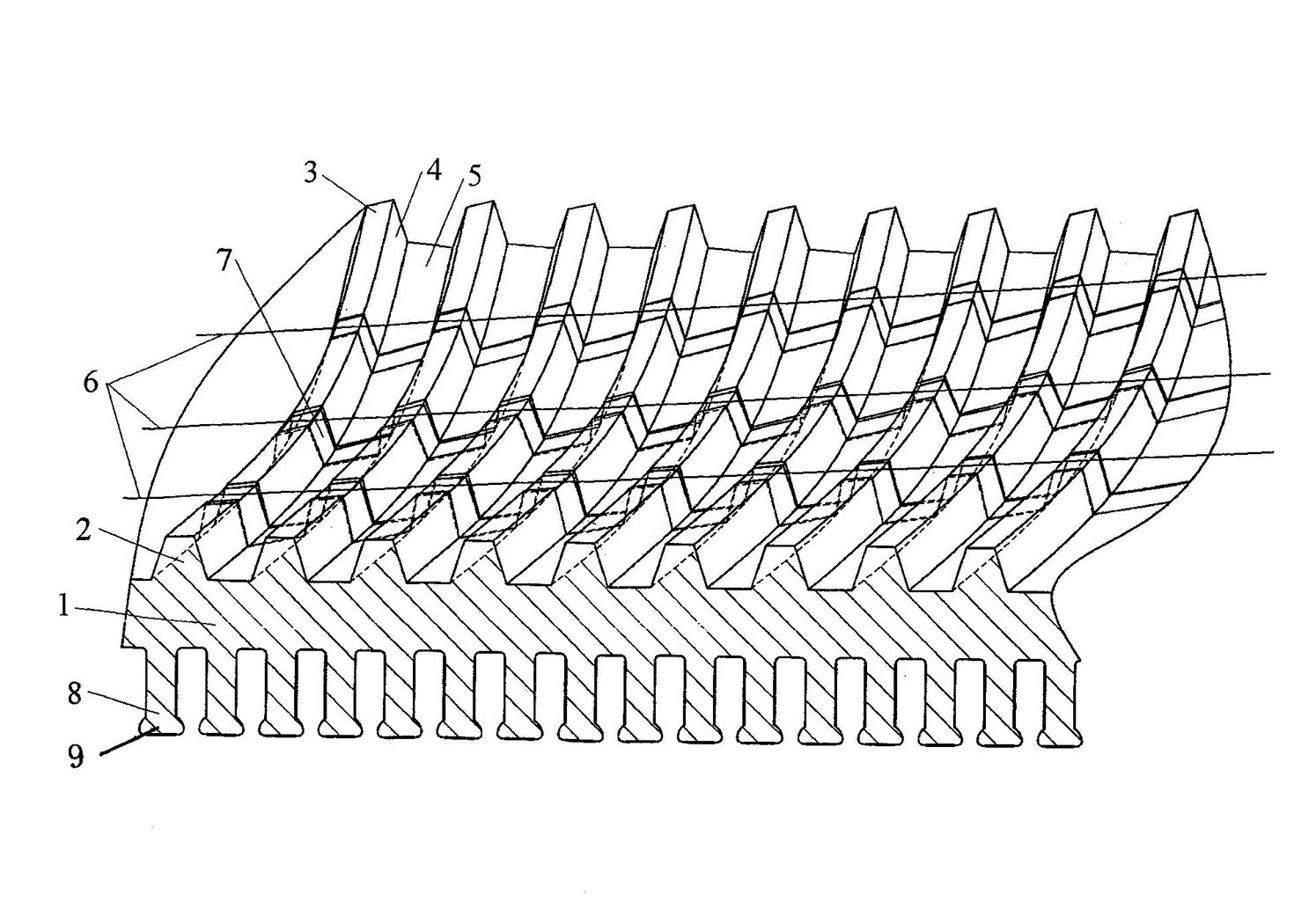
[0016] Example 1: See figure 1 , figure 2 and image 3 , the pipe body 1 is given, the length of the pipe body 1 is not limited, that is to say, there is no need to limit the length of the pipe body 1 in the present invention. Outer fins 8 are formed on the outer wall of the tube body 1. Preferably, fin top bosses 9 can be formed at the top of the outer fins 8, and the width between the fin top bosses 9 on adjacent outer fins 8 is smaller than the corresponding width. Width between adjacent outer fins 8 .

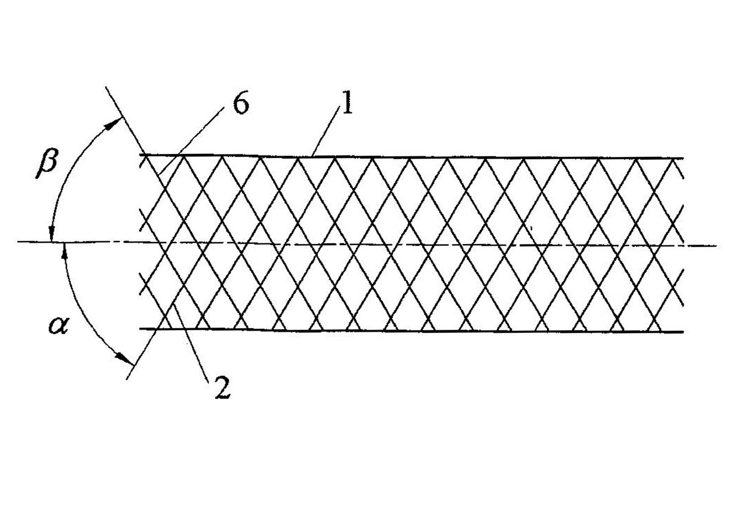
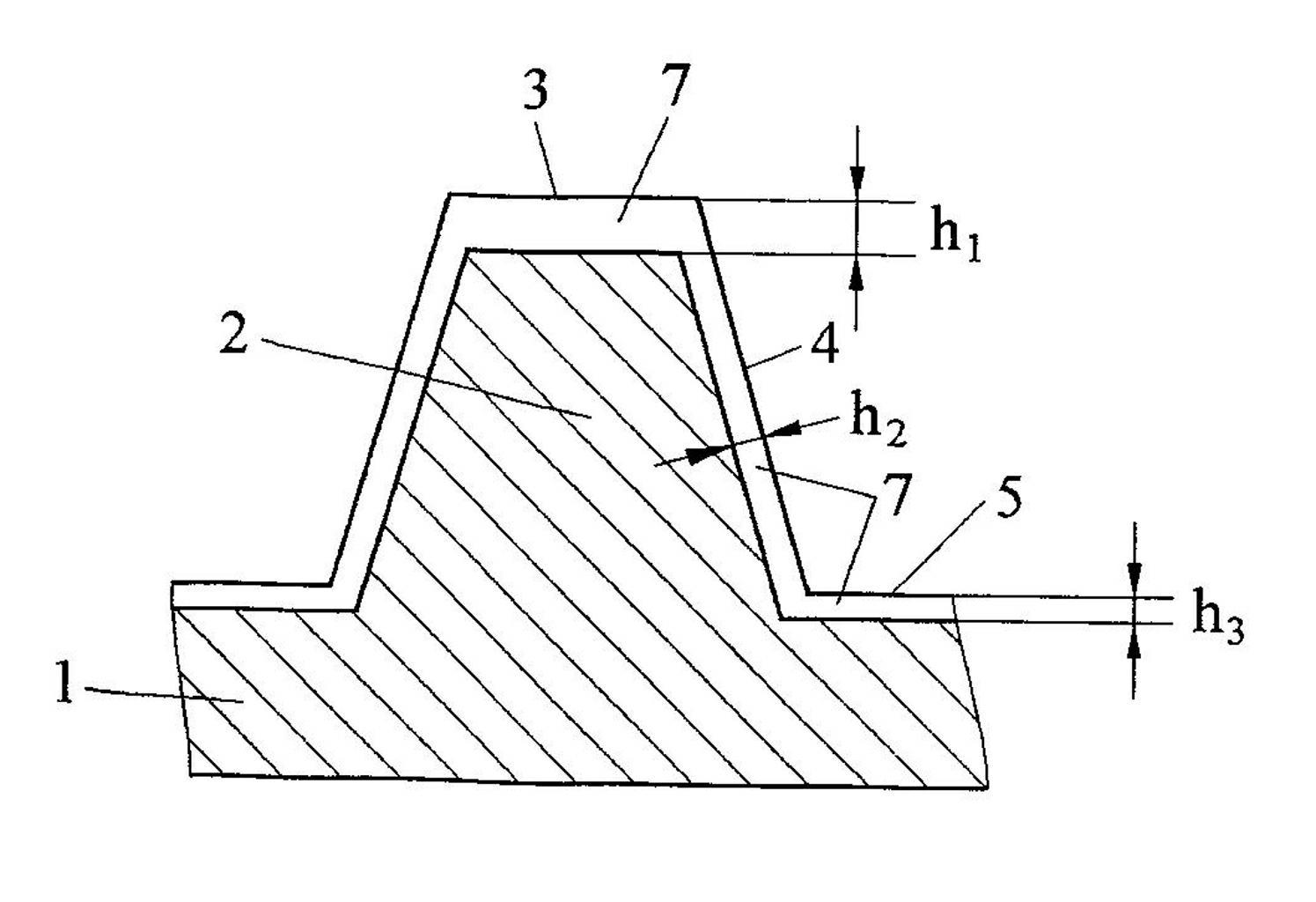
[0017] Spiral fins 2 are formed on the inner wall of the pipe body 1, and a set of grooves 7 are formed on the spiral fins 2 at intervals, that is to say, a group of grooves 7 spaced apart from each other are cut out on the spiral fins 2 by a cutter. , each groove 7 extends along the direction of the helix 6 from one end of the inner wall of the tubular body 1 toward the other end of the inner wall of the tubular body 1, more specifically along the helical fin on...

Embodiment 2

[0020] Figure omitted, only the first depth h 1 Change to 1.0㎜, the second depth h 2 Change to 0.5㎜, the third depth h 3 Changed to 0.1㎜, the cross-sectional shape of the groove 7 is arc-shaped, the width of the groove 7 is 2.5㎜, the angle of the first included angle α is 90°, and the angle of the second included angle β is 55°. The distance between the grooves 7 is 3.5mm. All the other are the same as the description to embodiment 1.

Embodiment 3

[0022] Figure omitted, only the first depth h 1 Change to 0.2㎜, the second depth h 2 Change to 0.03㎜, the third depth h 3 Changed to 0.08㎜, the cross-sectional shape of the groove 7 is triangular, the width (average width) of the groove 7 is changed to 1.5㎜, the angle of the first included angle α is changed to 65°, and the angle of the second included angle β is 0 °, the distance between adjacent grooves 7 is changed to 1.0mm. All the other are the same as the description to embodiment 1.


PUM


Abstract

The invention relates to a heat-exchange tube and belongs to the technical field of enhancement of heat transfer and energy saving. The heat-exchange tube comprises a tube body, wherein the wall face of the tube body is provided with spiral fins. The heat-exchange tube is characterized in that: a group of concave passages which are spaced are formed on the spiral fins; and the concave passages extend along the direction of a spiral line, extend from the surface of a tube base at one end of the tube body to the top of a first spiral fin along one side face of the first spiral fin, extend to the other side face of the first spiral fin after passing through the top of the first spiral fin, then, extend to the surface of the tube base located between two adjacent spiral fins, and further, extend to the side face and the top of a next spiral fin till extending to the surface of the tube base at an outer side of a side face of a last spiral fin at the other end of the tube body. The heat-exchange tube has the advantages of contributing to remarkably increasing a heat-exchanging area so as to improve the heat-exchanging performance and being beneficial to avoiding increasing the flow resistance of a fluid.

Description

technical field [0001] The invention belongs to the technical field of heat transfer enhancement and energy saving, and in particular relates to a heat exchange tube used in air-conditioning and refrigeration systems. Background technique [0002] In the prior art, in order to improve the heat exchange efficiency of heat exchange tubes used in air-conditioning and refrigeration systems, low-finned tubes are generally used to increase the heat exchange area, and at the same time enhance the heat exchange surface to enhance the fluid disturbance to enhance the heat exchange effect. Chinese utility model patent ZL99228089.3, Chinese invention patent ZL95121709.7 and Chinese utility model patent ZL02232596.4 disclose a heat transfer tube with a three-dimensional low-fin structure. A group of main grooves are cut out on the tube wall to form fins. , and then cut a set of intersecting spiral grooves (secondary grooves) on the fins to form tooth-shaped spiral fins. Not limited to ...

Claims


Application Information

Patent Timeline
Patent Type & Authority Applications(China)
IPC IPC(8): F28F1/42
Inventor 陆明华张春明周浩平罗行景晓伟
Owner JIANGSU CUILONG PRECISION COPPER TUBE CORP
Why Eureka
Try Eureka