
Rotary current stabilizer

A current stabilizer and rotary technology, which is applied in the direction of instruments, fluid velocity measurement, and measurement flow/mass flow, etc., can solve the problems of decreased measurement accuracy, increased probability of turbulent vortex flow, unstable fluid, etc., to achieve the goal of containing The effect of reducing the diffusion rate of substances, reducing the probability of eddy flow, and reducing the pulsation amplitude

Active Publication Date: 2012-11-28
WEIHAI PLOUMETER
View PDF4 Cites 0 Cited by
  • Summary
  • Abstract
  • Description
  • Claims
  • Application Information

AI Technical Summary

Problems solved by technology

[0002] At present, in the measurement of heat meters and water flow, it is mainly realized by placing one or more pairs of ultrasonic transducers at both ends of the pipe under test. The flow velocity of the fluid is calculated by obtaining the forward and reverse propagation velocity difference of the sound wave, and then the flow rate is calculated by the integral formula integrated in the PCB board chip. The above is an ideal situation for a stable fluid. The complex situation at the front end, such as the influence of elbows, variable diameters, valves, filters, etc., makes it difficult to obtain a stable ideal fluid flowing through the flowmeter, and unstable fluid affects the accuracy of the measured data
In order to eliminate the influence and obtain a stable fluid, some straight flow stabilizers are installed at the inlet of the flowmeter, but due to the influence of the length of the meter body, the straight flow stabilizers can only be made very short, thus playing a role The effect of steady flow is also very small; in some measuring pipes, the two ends of the steady flow pipe body are respectively equipped with reflector bases, and four reflector brackets are arranged on the base, and the reflector frame is installed in the center of the base through the reflector brackets. The upper end of the frame is connected to the upper end of the mirror bracket, and the lower end is connected to the lower end of the mirror bracket. When the unstable fluid passes through the ultrasonic stroke area, the fluctuating fluid passes through one or more pairs of ultrasonic transducers under the reaction of the mirror bracket. The flow velocity of the fluid is calculated based on the difference between forward and reverse propagation speeds of the sound waves measured by the instrument. The shortcoming is that since the mirror bracket is installed in the pipeline, the irregular shape of the bracket directly changes the flow state of the fluid when the water flows through it. , leading to large pulsation amplitude of turbulent fluid, increasing the probability of turbulent eddy flow, thus affecting the accuracy of ultrasonic measurement and reducing the accuracy of ultrasonic flowmeter
[0003] In addition, during the use of the heat meter, a filter is usually installed at the front of the heat meter to increase the measurement accuracy and also for the protection of the heat meter, but the flow state of the water will change after the filter is installed, As a result, the measurement accuracy is reduced, and the measurement cost is also increased.

Method used


Image

  • Rotary current stabilizer
  • Rotary current stabilizer
  • Rotary current stabilizer

Examples


Embodiment 1

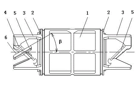
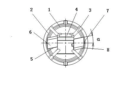
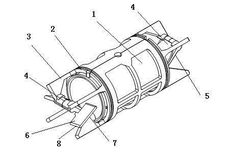
[0022] Embodiment 1: the present invention can have 2 rotating vanes 5 in the side circumferential array of mirror frame 4, and rotating vane 5 is square plate shape, and the angle between the upper surface 6 of rotating vane 5 and its outer side 7 is 80 °, so that The radial deflection angle of the rotating blade 5 relative to the steady flow pipe body 1 α is 10°, the upper end surface 8 is a transitional arc surface, in order to reduce the resistance of the fluid and avoid the pulsation amplitude, the rotating blade 5 is axially inclined, and the angle between the inclined surface 6 and the axis of the steady flow pipe body 1 β Between 20° and 45°, it is beneficial to guide the unstable fluid through the rotating blade 5 to form a stable swirling fluid, so that the flow velocity of the fluid passing through the ultrasonic region reaches a stable state, which has the effect of accurate measurement.

Embodiment 2

[0023] Embodiment 2: The present invention can have 4 rotating blades 5 in the circumferential array between mirror bracket 2, and rotating blade 5 is fixedly connected with mirror bracket 2 through connecting block 9, and the upper end surface of rotating blade is from the inside to the outside and between the mirror bracket. The connecting surface between them is arc-shaped transition, and the angle between the upper surface of the rotating blade and the outer surface is 80°, so that the radial deflection angle of the rotating blade relative to the steady flow pipe body α 10°, in order to reduce fluid resistance and avoid pulsation amplitude, the rotating blade 5 is axially inclined, and the angle between the inclined surface 6 and the axis of the steady flow pipe body 1 β Between 20° and 45°, it is beneficial to guide the unstable fluid through the rotating blade 5 to form a stable swirling fluid, so that the flow velocity of the fluid passing through the ultrasonic region c...


PUM


Abstract

The invention relates to a fluid metering device and particularly relates to a rotary current stabilizer. The rotary current stabilizer is provided with an anemostat body, wherein the two ends of the anemostat body are respectively and correspondingly provided with a reflector base; the reflector bases are provided with reflector brackets; and reflector frames are arranged at the centers of the reflector bases through the reflector brackets. The rotary current stabilizer is characterized in that 2-4 rotating blades are circumferentially arrayed between the brackets at the outer sides of the reflector frames; the rotating blades are in the shape of a square plate; and the included angle between the upper surface and outside surface of each rotating blade is 80 degrees, so that the radial deflection angle, relative to the anemostat body, of each rotating blade is 10 degrees; the upper end face of each rotating blade is of a transitional arc-shaped face, thereby being beneficial to the reduction of the fluid resistance and avoiding the pulsation amplitude; and each rotating blade inclines axially, so that the included angle between each inclined face and the axis of the anemostat body is between 20 degrees and 45 degrees. Based on such a structure, the rotary current stabilizer has the advantages of novel structure, balanced current speed, accuracy in measurement and the like.

Description

Technical field [0001] The metering of the current invention involving a fluid is a rotary stabilizer that improves the measurement accuracy of the flow meter measuring meter. Background technique [0002] At present, in terms of the measurement of the heat meter and water flow flow, it is mainly implemented through one pair or more to the ultrasonic converter at both ends of the test pipeline. The ultrasonic flow meter uses the principle of transmission in the liquid by ultrasonic waves. Through the measurement, the test is tested.Calculate the flow rate of the fluid in the direction of the sound wave and the reverse transmission speed, and then calculate the traffic by the integration of the PCB board chip. The above is the ideal situation of the stable fluid.The complicated situation of the front end, if there is the effect of bending tube, variable diameter, valve, filter, etc., it is difficult to obtain stable ideal fluid flowing through the flowmeter, and unstable fluids ca...

Claims


Application Information

Patent Timeline
Patent Type & Authority Patents(China)
IPC IPC(8): G01F1/66G01F15/00G01P5/24
Inventor 付涛徐军左林
Owner WEIHAI PLOUMETER
Learn More