Shower separating device

A separation device and transmission device technology, applied in door/window protection devices, window decorations, shading screens, etc., can solve problems such as wear and tear, and achieve the effect of simple replacement

Inactive Publication Date: 2012-04-25
KLEINE WOLKE TEXTILGMBH BESCHRAENKTERHAFTUNG
View PDF5 Cites 0 Cited by
  • Summary
  • Abstract
  • Description
  • Claims
  • Application Information

AI Technical Summary

Problems solved by technology

[0004] The angular shower curtain known from the prior art has the disadvantage that it can only be used in right-angled bathtubs (Badewannen) and / or shower cabins (Duschwannen)
Furthermore, torque transmission is always hakelend and lossy

Method used


Image

  • Shower separating device
  • Shower separating device

Examples


Embodiment Construction

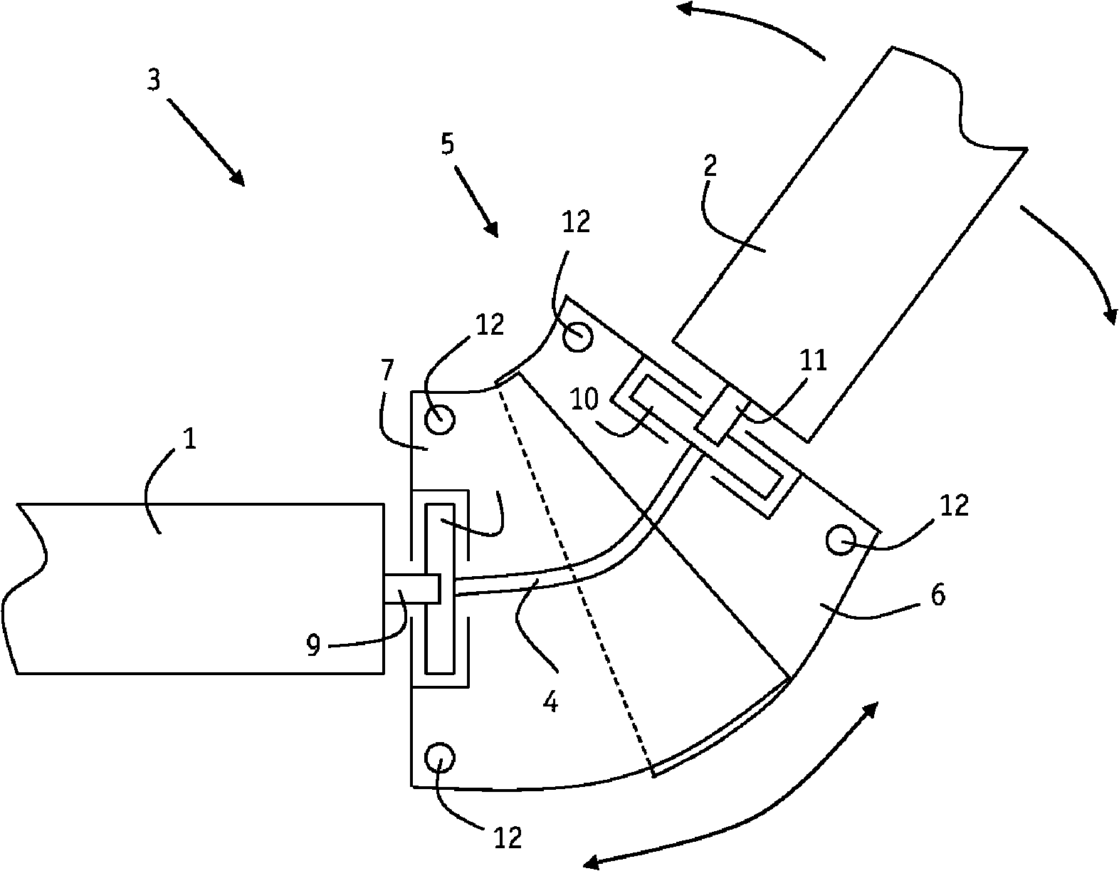
[0019] figure 1 Shows a shower divider according to the invention with a first rotatably mounted roller body 1 and a second rotatably mounted roller body 2 on which at least one shower curtain can each be wound (not shown). A transmission 3 is provided for transmitting the rotational movement of one roller body to the other roller body. The transmission 3 has a bendable shaft 4 , which is rotatably mounted with its ends in a housing 5 . The housing 5 has two housing parts 6 , 7 that are movable (ie deflectable) relative to each other. One end of the bendable shaft 4 is connected in a rotationally fixed manner to a first bearing race 8 which is rotatably mounted in the first housing part 7 . The bearing race 8 has an opening into which the coupling shaft 9 of the first roller body 1 can be inserted in a rotationally fixed manner. Similarly, at its other end, the bendable shaft 4 has a second bearing race 10 which receives the second coupling shaft 11 of the second roller bo...


PUM


Abstract

The invention relates to a shower separating device comprising at least two rotatably supported roll-up elements, on which at least one shower curtain can be rolled up, and having a transmitting device for transmitting a rotational motion of one roll-up element to the other roll-up element, wherein with regard to universal and reliable usability, said shower separating device is designed in such a way that the transmitting device has a flexible shaft.

Description

technical field [0001] The invention relates to a shower divider with at least two rotatably mounted rollers on which at least one shower curtain can each be wound, and a drive for It is used to transfer the rotational motion of one roller body to the other roller body. Background technique [0002] From DE 198 14 391 C1 a hinged connection assembly for a shower partition (ie two or more shower roller blinds) is known. The connecting assembly has a housing for accommodating the transmission, wherein the housing has a bearing carrier with at least two bearing surfaces arranged at an angle to one another. The bearing surface is provided with holes for receiving the main journals. The main journal is a component part of the insert, into which the respective ends of the roller blind shaft can be inserted or pressed in a rotationally fixed manner. The housing has a frame extending substantially parallel to the support surface, the frame being connected to a support surface, wh...

Claims


Application Information

Patent Timeline
Patent Type & Authority Applications(China)
IPC IPC(8): A47K3/38
CPCA47K3/38E06B9/42E06B2009/1746
Inventor J・霍夫曼C・拉姆拉斯J・加福特
Owner KLEINE WOLKE TEXTILGMBH BESCHRAENKTERHAFTUNG
Why Eureka
Try Eureka