Connecting device between a friction ring and a hub of a brake disk

A connecting device and friction ring technology, applied in the direction of brake components, brake discs, brake types, etc., can solve problems such as disc failure, and achieve the effect of great flexibility and looseness avoidance

Inactive Publication Date: 2013-02-27
AUDI AG
View PDF3 Cites 3 Cited by
  • Summary
  • Abstract
  • Description
  • Claims
  • Application Information

AI Technical Summary

Problems solved by technology

This can cause

Method used


Image

  • Connecting device between a friction ring and a hub of a brake disk
  • Connecting device between a friction ring and a hub of a brake disk
  • Connecting device between a friction ring and a hub of a brake disk

Examples


Embodiment Construction

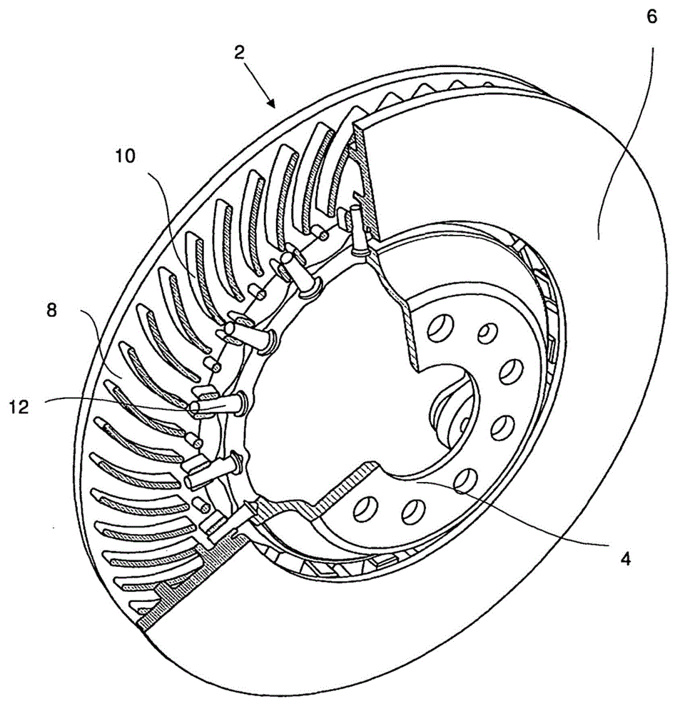
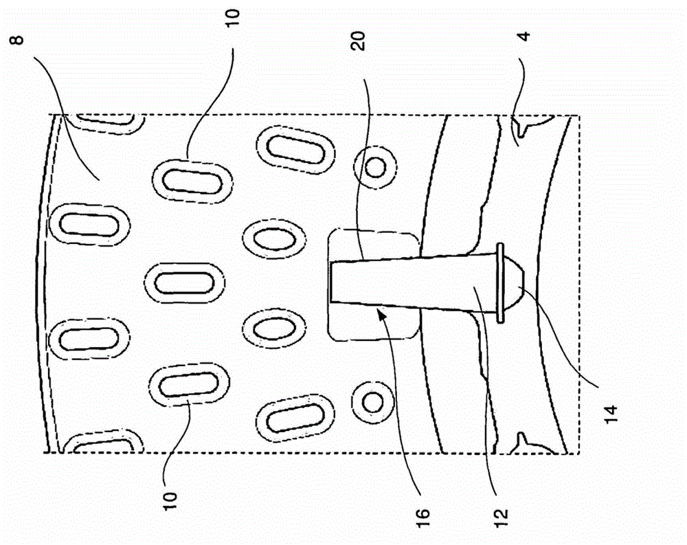
[0020] The figures show an exemplary embodiment of a connecting device according to the invention for a brake disc with a friction ring 2 and a carrier part 4 . as from figure 1 and image 3 As can be seen in , the friction ring 2 is composed of two friction ring halves, of which one friction ring half forms the outer wall 6 of the friction ring 2 and the other friction ring half forms the inner wall 8 . The two friction ring halves are connected to each other by laminations 10 which provide cooling of the brake disc during operation.

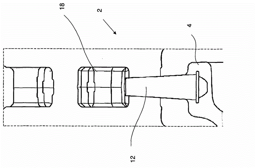
[0021] The connection between the friction ring 2 and the carrier part 4 is formed by a connecting part 12 which can be designed as a pin or as a small tube. As a result, the friction ring 2 is mounted floatingly on the carrier part 4 , whereby it can expand in the radial direction when the temperature increases. The anchoring of the connection part 12 in the carrier part 4 and the assembly of the friction disk as a whole is carried out in a...


PUM


Abstract

The invention relates to a connecting device between a friction ring (2) and a support part (4) of a brake disk, wherein the friction ring (2) is connected to the friction ring (2) by means of connecting elements (12), wherein a plurality of connecting elements (12) arranged in a distributed manner over the circumference of the support part (4) and connected to the support part (4) protrude into openings in a radially inner circumferential wall of the friction ring (2), wherein the holes (20) in the friction ring (2) and the connecting elements (12) are conical, and wherein the conical hole in the friction ring (2) is extended radially inwardly and the conical connecting elements (12) are tapered radially outwardly. In a method for designing or producing the connecting device, the holes (20) in the friction ring (2) and the connecting elements (12) are designed to be correspondingly conical.

Description

technical field [0001] The invention relates to a connection device between a friction ring of a brake disc and a bowl, wherein the friction ring is connected to the friction ring through a connecting piece, wherein a plurality of friction rings are distributed on the circumference of the carrier The connection element, which is arranged in a grounded manner and is connected to the carrier element, protrudes into a recess in the radially inner circumferential wall of the friction ring. Background technique [0002] From DE 43 32 951 A1 a brake disc is known, in particular a ventilated brake disc, with a friction ring and a carrier part connected to the friction ring via a connecting part, wherein several The connection elements to the carrier project in the form of bolts, pins or the like into recesses in the circumferential wall of the friction ring. The pins protrude radially from the circumferential wall of the carrier and into bores in the inner circumferential wall of ...

Claims


Application Information

Patent Timeline
IPC IPC(8): F16D65/12F16D65/14
CPCF16D65/0043F16D2065/1344F16D65/123F16D2250/0015F16D2065/1376F16D2065/1316F16D2065/1328F16D2065/136F16D2065/1392Y10T29/49826
Inventor K·弗尔斯特C·萨米
Owner AUDI AG
Why Eureka
Try Eureka