Bone dissociation device

A disconnection and sliding installation technology, applied in the field of medical devices, can solve the problems of unguaranteed safety, bone splitting at the disconnection site, uncertain shape of the bone fracture end, etc., to avoid repeated injuries.

Pending Publication Date: 2020-04-03
PLASTIC SURGERY HOSPITAL CHINESE ACAD OF MEDICAL SCI
View PDF0 Cites 1 Cited by
  • Summary
  • Abstract
  • Description
  • Claims
  • Application Information

AI Technical Summary

Problems solved by technology

This operation uses oscillating saws of different lengths to cut the mandibular angle sequentially on the planned osteotomy line, but it is difficult to fully expose and effectively treat the distal end of the posterior wall of the ascending ramus of the mandibular angle during the cutting of the osteotomy line , there are often residual bone connections, and there is a problem that it is difficult to cut off the posterior wall of the ramus of the mandible, and because there are abundant tissues and blood vessels that are difficult to find around the deep part, if cut off rashly, it will cause unpredictable damage. For the sake of safety, it is usually preferred to leave 2-5mm of residual bone connection, and then use a bone breaking device to cut off the remaining 2-5mm of bone connection
[0003] At present, the conventional disconnection scheme used to cut off the remaining 2-5mm residual bone connection is to fix the osteotome at the specific site of the residual bone connection, use a hammer to hammer the osteotome and align it with the broken site to impact the bone to remove the residual bone. The bone connection is disconnected, but it is not easy to grasp the magnitude and direction of the force during operation, and it is impossible to guarantee one-time disconnection. Repeated operations are often required, and it is easy to damage important blood vessels and soft tissues around the bone at the site of the fracture. It is difficult to ensure the shape of the broken end, and it is easy to cause bone splitting at the severed site; and after the severed tool impacts and breaks the residual bone connection, the shape of the broken bone is uncertain, and because the anatomical part is deep, it is difficult to trim and polish. It often leads to unpredictable side effects after surgery; moreover, if the bone chisel is used to cut off the bone, the resulting broken bone will also damage the surrounding tissue due to its sharpness, so the safety is not guaranteed, and even the split is severe. The fracture line goes upward into the temporomandibular joint, resulting in more serious consequences

Method used


Image

  • Bone dissociation device
  • Bone dissociation device
  • Bone dissociation device

Examples


Embodiment 1

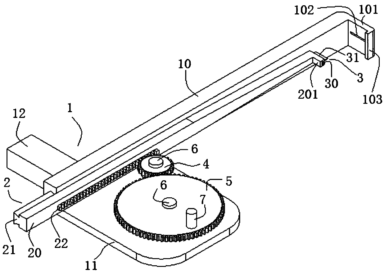
[0052] This embodiment provides a bone breaking device, such as Figure 1 to Figure 3 As shown, it includes: a base 1, a rod body structure 10 is provided on the base 1, one end of the rod body structure 10 is connected to the base 1, and the other end extends outward to form an extension end; On the rod body structure 10, the end of the extended end of the broken knife handle structure 2 near the rod body structure 10 is provided with a broken knife 3, and the end of the extended end of the rod body structure 10 is provided with a retaining hook structure for blocking the broken knife 3; the driving mechanism , which is connected with the breakaway handle structure 2, and is used to drive the breakaway knife handle structure 2 to move along the length direction of the rod structure 10 close to the retaining hook structure.

[0053] In this example, if Figure 1 to Figure 3 As shown, the base 1 is provided with a rod body structure 10, and the breaking tool handle structure 2...

Embodiment 2

[0071]The second embodiment is basically the same as the first embodiment, except that:

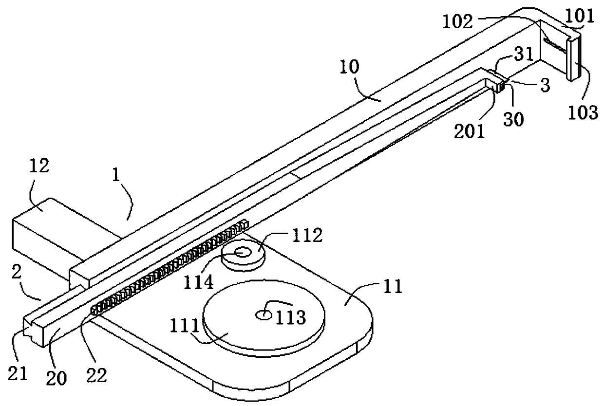
[0072] In this example, if Figure 7 , Figure 8 As shown, the guide groove 104 in this embodiment is provided on the upper side of the rod structure 10, the guide groove 104 extends from the front end surface of the rod structure 10 to the middle position of the rod structure 10, and the cross section of the guide groove 104 is an isosceles trapezoidal structure . In this embodiment, the front part of the knife handle body 20 is in the shape of a cuboid, and the end of the knife handle body 20 close to the blocking structure 101 is designed as a tapered wedge-shaped structure.

[0073] In this example, if Figure 7 , Figure 8 As shown, the blocking structure 101 is connected to the upper side of the rod structure 10, and the side of the blocking structure 101 facing the breaking knife 3 is provided with a groove 102 that can avoid the cutting edge of the breaking knife 3, which is b...

Embodiment 3

[0075] The third embodiment is basically the same as the first embodiment, except that:

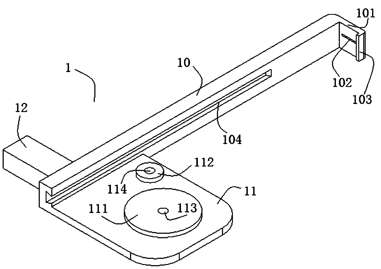
[0076] In this embodiment, the rod body structure 10 includes a connected straight end and a curved end; one side of the straight end is provided with a guide groove 104 adapted to the guide slide rail 21 along the length direction of the straight end, and the guide groove 104 The curved end extends along the bending direction of the curved end, the cross section of the guide groove 104 is an arc-shaped hole, and the guide rail 21 is adapted to be slidably installed in the guide groove 104; the broken knife handle structure 2 includes a bendable curved knife handle structure and The drive handle body used to push the movement of the first connecting block 23; the curved handle structure includes the first connecting block 23 and the tail connecting block 25, the first connecting block 23 includes a body one 231, and a support protrusion one 233 for slidingly supporting the body one 231 , ...


PUM


Abstract

The invention discloses a bone dissection device, which belong to the technical field of medical instruments. The device comprises a base, a rod body structure is arranged on the base, one end of therod body structure is connected to the base, and the other end of the rod body structure extends outwards to form an extending end; a dissociation knife handle structure is installed on the rod body structure in a sliding mode, a dissociation knife is arranged at the end, close to the extending end of the rod body structure, of the dissociation knife handle structure, and a blocking hook structureused for blocking the dissociation knife is arranged at the end of the extending end of the rod body structure; and a driving mechanism is connected with the dissociation knife handle structure and used for driving the dissociation knife handle structure to move close to the stop hook structure in the length direction of the rod body structure. When the bone dissociation device is used for dissociating bone substances, the bone dissociation end is smooth and free of angles, more time does not need to be wasted for trimming the dissociation end, subsequent operation steps are convenient to carry out, and the risk of bone dissociation is effectively reduced.

Description

technical field [0001] The invention relates to the technical field of medical instruments, in particular to a bone breaking device. Background technique [0002] The development of bone plastic technology is closely related to the development and practicality of surgical instruments. For the safety and accuracy of surgery, it is necessary to equip high-efficiency special instruments suitable for specific anatomical parts before surgery. Osteotomy is a commonly used bone plastic technology. The treatment plan is usually applied to diseases such as osteonecrosis, comminuted fracture and dislocation that cannot be reduced, bone defect, shortened limbs, orthopedic reduction, etc. Among them, for the operation of disconnecting the bone connection of a specific deep anatomical part, such as mandibular surgery in maxillofacial surgery, an intraoral incision is selected during the operation, and the exposure of the surgical field is limited. Muscle and soft tissue, although it is ...

Claims


Application Information

Patent Timeline
Patent Type & Authority Applications(China)
IPC IPC(8): A61B17/16F16H19/04
CPCA61B17/1657F16H19/04
Inventor 张栋靳小雷郭小双杜宏宋国栋宗宪磊都乐赵竟伊杨常盛相贵华
Owner PLASTIC SURGERY HOSPITAL CHINESE ACAD OF MEDICAL SCI
Why Eureka
Try Eureka