Exhaust structure of vacuum pump

A technology of vacuum pump and exhaust port, which is applied in the direction of pump, parts of pumping device for elastic fluid, pump element, etc., to achieve the effect of increasing exhaust area, good stability and avoiding damage

Active Publication Date: 2017-10-24
ZHEJIANG VACUUM EQUIP GROUP +1
View PDF8 Cites 3 Cited by
  • Summary
  • Abstract
  • Description
  • Claims
  • Application Information

AI Technical Summary

Problems solved by technology

[0004] The purpose of the present invention is to solve the above-mentioned problems in the existing technology, and propose a vacuum pump exhaust structure. The technical problem to be solved by the present invention is: how to reduce the noise generated during exhaust and prolong the service life

Method used


Image

  • Exhaust structure of vacuum pump
  • Exhaust structure of vacuum pump
  • Exhaust structure of vacuum pump

Examples


Embodiment Construction

[0027] The following are specific embodiments of the present invention in conjunction with the accompanying drawings to further describe the technical solutions of the present invention, but the present invention is not limited to these embodiments.

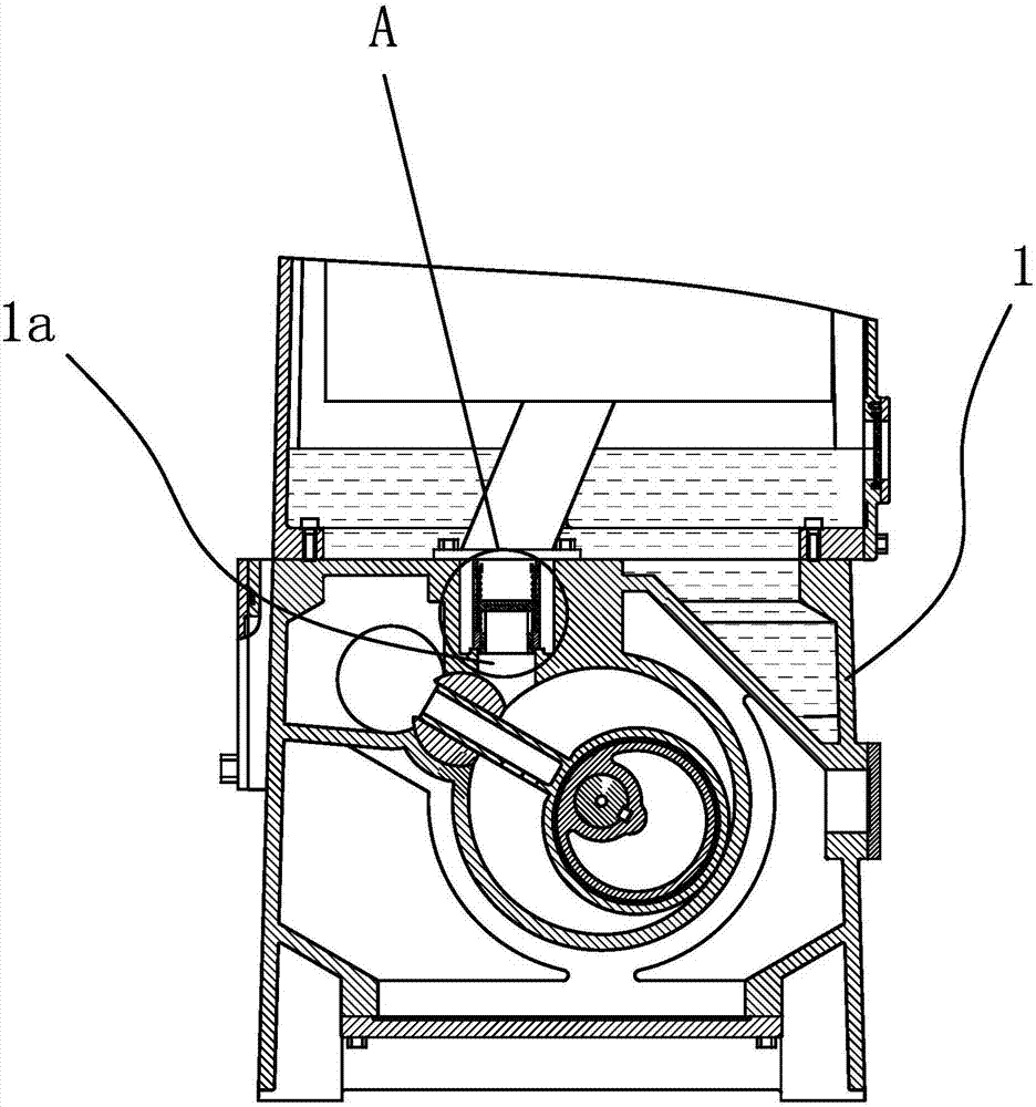
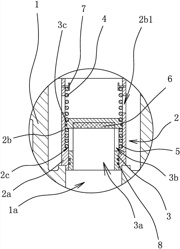
[0028] Such as figure 1 with 2 As shown, the vacuum pump includes a pump body 1 with an exhaust port 1a. The exhaust structure includes a cylindrical valve seat 2 and a valve core 3 slidably connected to the valve seat 2. The valve seat 2 is fixed on the exhaust of the pump body 1. Port 1a.

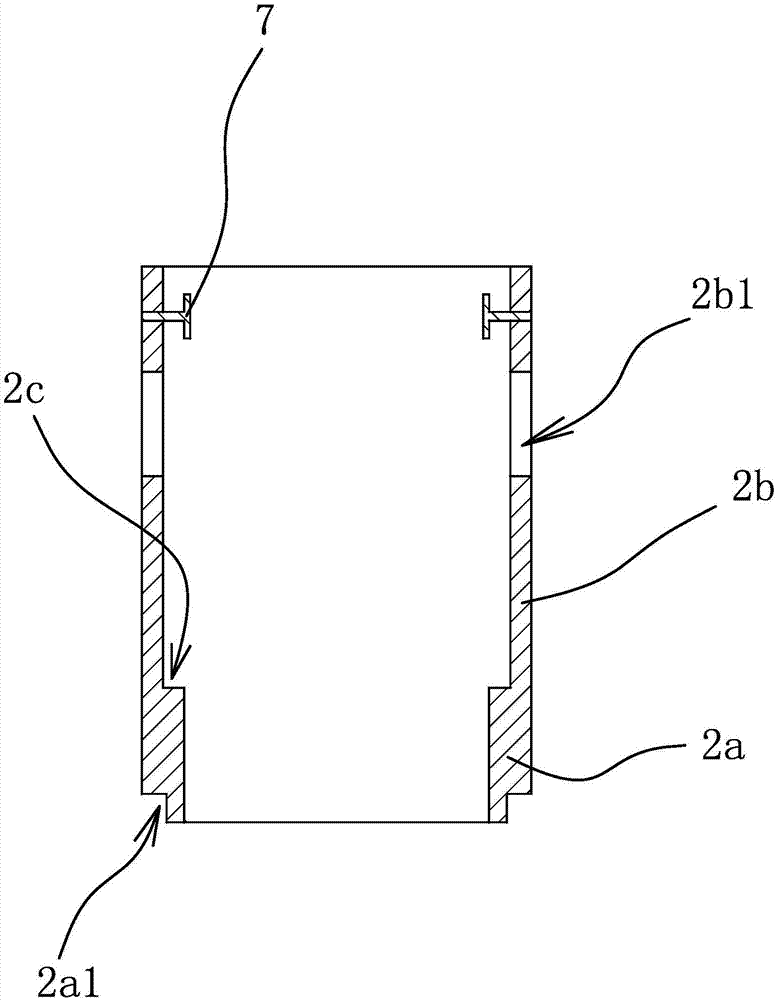
[0029] Specifically, such as figure 2 with 3 As shown, the valve seat 2 includes a connecting section 2a and a sealing section 2b, and the inner diameter of the connecting section 2a is smaller than the inner diameter of the sealing section 2b. The connecting section 2a has an annular concave shoulder 2a1 on the outer side wall of one end away from the sealing section 2b. The connecting section 2a is fixedly inserted into the exhaust port 1a, an...


PUM


Abstract

The invention provides an exhaust structure of a vacuum pump, and belongs to the technical field of machinery. The problem that a conventional exhaust structure is high in noise and liable to damage is solved. The exhaust structure of the vacuum pump comprises a valve seat and a valve core, wherein one end of the valve seat is open; the open end is connected to an exhaust opening of a pump body and communicates with the exhaust opening; gas outlets are formed in the side wall of the valve seat; the outer side wall of the valve core and the inner wall of the valve seat are sealed; the outer side wall of the valve core can slide along the inner wall of the valve seat; an elastic part I and an elastic part II are further arranged in the valve seat; the elastic part I abuts against one end of the valve core; the sealing part of the outer side wall of the valve core and the inner wall of the valve seat is positioned between the exhaust opening and the gas outlets under the action of the elastic part I; and the two ends of the elastic part II separately abut against the other end of the valve core and the valve seat. According to the exhaust structure of the vacuum pump, a high-pressure gas is directly exhausted from gas passing holes and the gas outlets, a reflux gas and the gas exhausted from the pump body are prevented from colliding with each other, secondary collision between the gas and the valve seat is avoided, and noise is reduced.

Description

Technical field [0001] The invention belongs to the technical field of machinery and relates to an exhaust structure of a vacuum pump. Background technique [0002] In recent years, the application of vacuum pumps in metallurgy, chemical, food, electronic coating and other industries has developed rapidly. The sliding valve vacuum pump is a variable-capacity gas transmission pump, which is widely used in industrial and scientific research experiments. It has the advantages of reliable work and convenient operation. The working principle of a vacuum pump is to suck gas from the air inlet, transfer and compress it in the pump cavity, and finally discharge it from the exhaust port through the exhaust valve. The sealing performance of the exhaust valve has a direct effect on the degree of vacuum obtained. [0003] Existing vacuum pump exhaust structures, such as a Chinese patent application (application number: 201420145647.9) discloses a vacuum pump exhaust valve assembly, which incl...

Claims


Application Information

Patent Timeline
Patent Type & Authority Applications(China)
IPC IPC(8): F04C29/12F04C29/00F04C25/02F04C29/06
CPCF04C25/02F04C29/00F04C29/063F04C29/128
Inventor 钟云会陈岚杨华飞罗根松黄智敏陈仙春王贵周君斐
Owner ZHEJIANG VACUUM EQUIP GROUP
Why Eureka
Try Eureka