Tracheostoma valve

A tracheostomy and air technology, applied in the direction of tracheal intubation, respirator, etc., can solve problems such as difficult to reach, conspicuous, and difficult to operate valves

Inactive Publication Date: 2012-04-25
UNIVERSITY OF GRONINGEN +1
View PDF4 Cites 4 Cited by
  • Summary
  • Abstract
  • Description
  • Claims
  • Application Information

AI Technical Summary

Problems solved by technology

For example, the suction valve remains expensive due to its many parts and needs to be maintained frequently, the valve remains difficult to operate (small setting knob), large, heavy, obtrusive and hard to reach

Method used


Image

  • Tracheostoma valve
  • Tracheostoma valve
  • Tracheostoma valve

Examples


Embodiment Construction

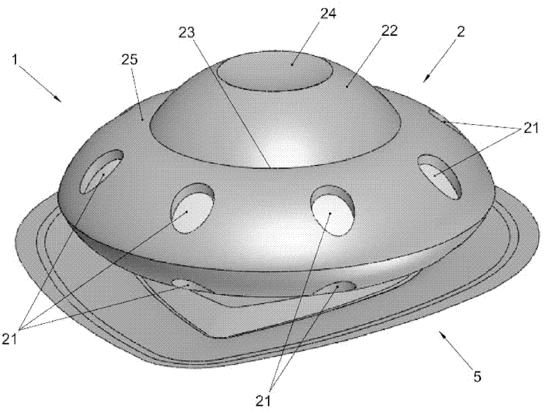
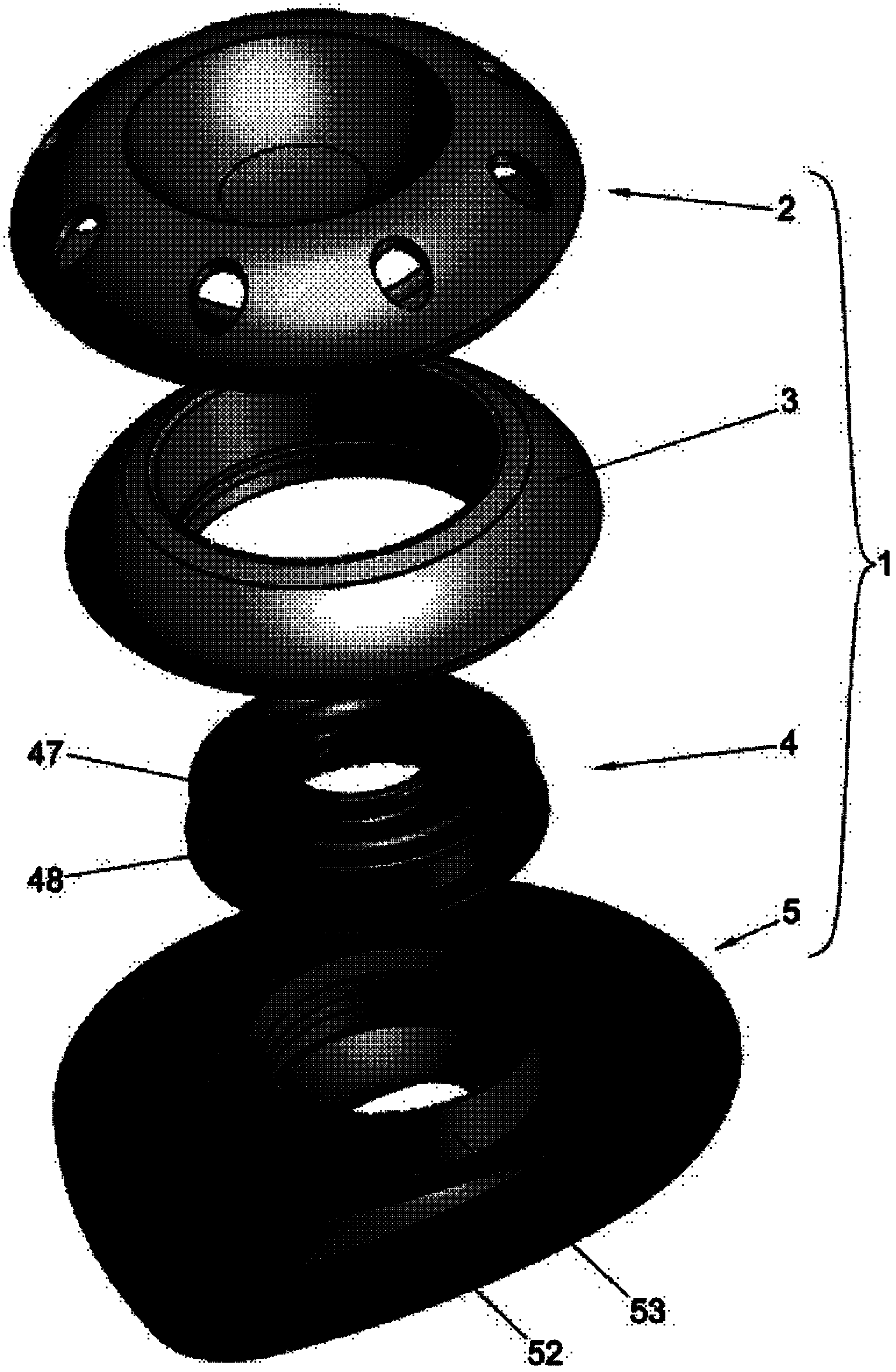
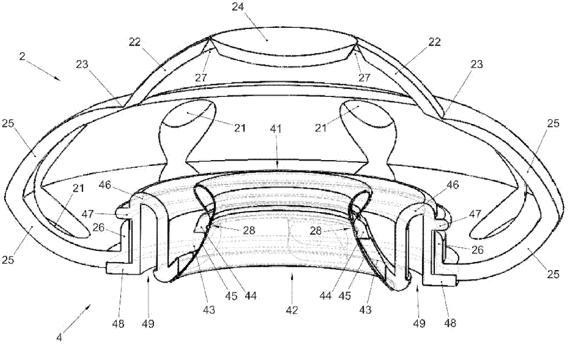
[0035] figure 1 and figure 2 An example of an embodiment of a tracheostomy valve 1 according to the invention is shown. The tracheostomy valve 1 shown comprises a cap 2 , a filter means 3 , a cap seat 4 and an attachment means 5 . Note that for simplicity, Filter Tool 3 is not in the image 3 and Figure 4 shown in .

[0036] The lid 2 comprises elastic main walls having a general shape more or less similar to the shape of a dome. The elastic main wall comprises wall sections 22, 24, 25, wherein the wall section 25 has a circumferential connecting flange 26 connecting the cover 2 to the cover base 4 (see image 3 and Figure 4 ). In the wall part 25 there are a number of breathing openings 21 . In the illustrated embodiment, some of the breathing openings 21 are circumferentially spaced relative to each other. The shown filter means 3 , for example of foam material, is substantially ring-shaped and in operation the filter means 3 is placed coaxially in the dome-shap...


PUM


Abstract

A tracheostoma valve (1) comprises a main air passage structure (21, 41, 42) provided with a main valve arrangement. The tracheostoma valve is switchable in response to a spurt of inhalation air from a breathing condition into a speaking condition, while the tracheostoma valve is switchable in response to a spurt of exhalation air from said speaking condition into said breathing condition. The main valve arrangement comprises an at least partly flexible bistable wall portion (22, 23, 24) which has a circumferential bordering edge (23). At least part of the bordering edge forms a hinging means around which the bistable wall portion is hingeable between a first stable position in which an orifice (41) of the main air passage structure is being blocked, and a second stable position in which said orifice is released.

Description

technical field [0001] The present invention relates to a tracheostomy valve comprising a main airway structure provided with a main valve arrangement. Background technique [0002] Severe cancers in the laryngeal or hypopharyngeal region often require total laryngectomy, the removal of the larynx, including the vocal cords. Reconstruction is performed by directing the trachea externally. The trachea then ends at an opening in the neck, a so-called "tracheostomy". Following this procedure, voice restoration is usually performed by tracheoesophageal puncture and insertion of a one-way valve ("bypass valve") at the puncture site. In other words, such a bypass valve is inserted in the wall between the trachea and the esophagus. By closing the tracheostomy (manually or with the help of a so-called "tracheostomy valve"), at the top of the esophagus, exhaled air flows through a bypass valve to an air chamber surrounded by soft tissue, which then vibrates and acts as New "sound...

Claims


Application Information

Patent Timeline
Patent Type & Authority Applications(China)
IPC IPC(8): A61M16/04
CPCA61M16/0468A61M16/1045
Inventor 爱德华·贝伦德·凡·德·厚文海斯备特斯·雅各布斯·费尔科克伯纳德斯·弗朗西斯克斯·奥古斯丁奴斯·玛丽亚·凡·德·兰
Owner UNIVERSITY OF GRONINGEN
Why Eureka
Try Eureka