

Process for making a glass brick and brick obtained by said process
A block and glass plate technology, applied to building materials, etc., can solve the problem that the isolation ability of known blocks is not completely satisfactory
- Summary
- Abstract
- Description
- Claims
- Application Information
AI Technical Summary
Problems solved by technology
Method used
Image

Examples
Embodiment Construction
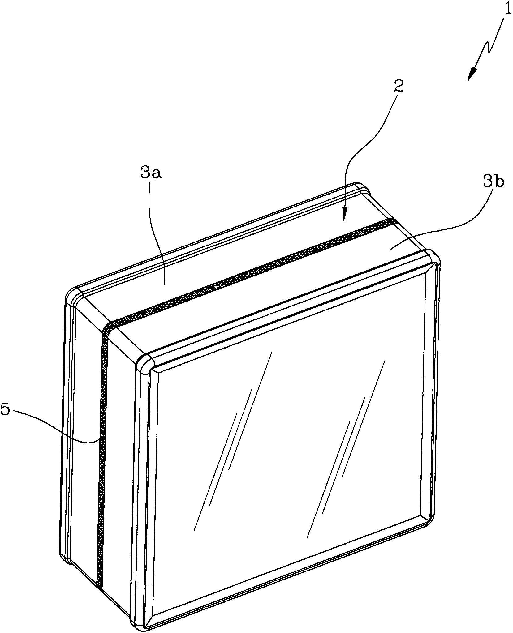
[0018] In the figures, the reference number 1 designates as a whole a glass block according to the invention. The block 1 comprises a body 2 made of transparent material. Preferably, this material is glass.
[0019] Advantageously, the body 2 has a substantially parallelepiped shape with a square base.
[0020] In an alternative embodiment (not shown), the body 2 has a substantially parallelepiped shape with a rectangular base.
[0021] In a further embodiment (not shown), such a body 2 may have, for example, a prismatic shape with a polygonal base.
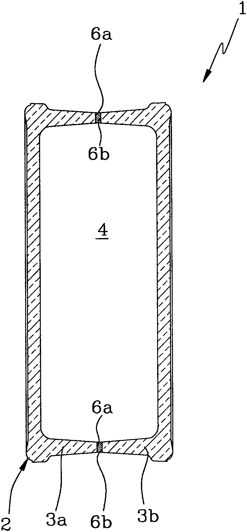
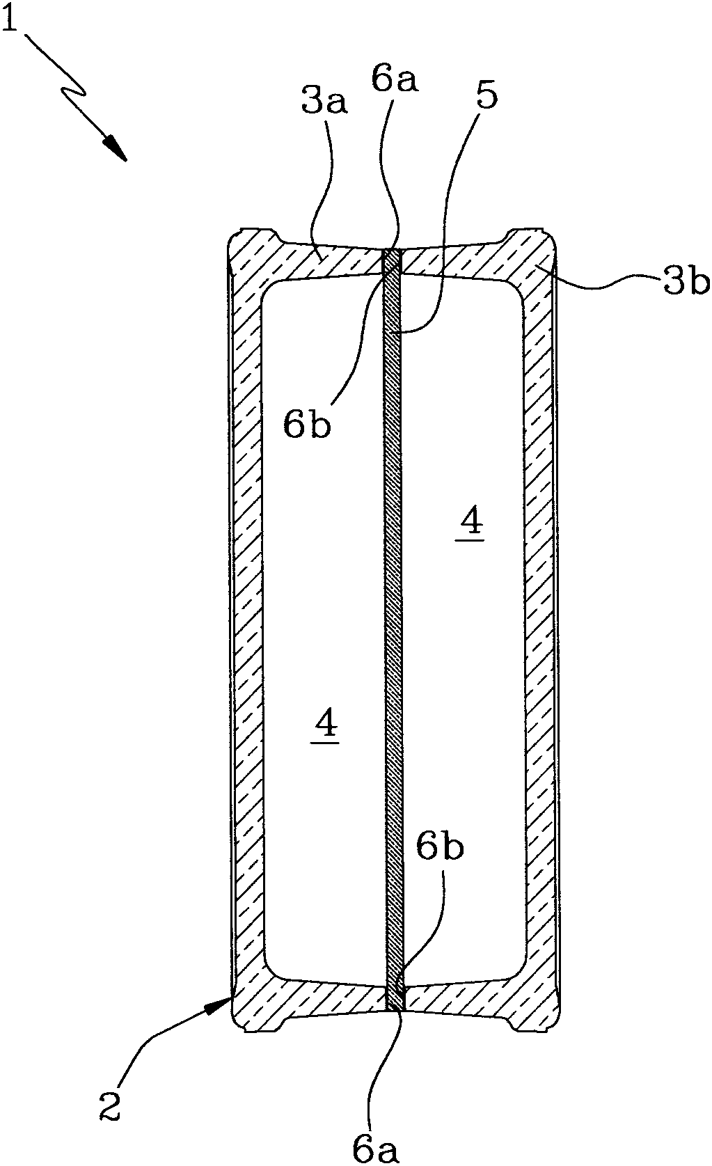
[0022] The body 2 comprises at least two half-shells 3 a , 3 b coupled to each other so as to define the same body 2 .
[0023] The half-shells 3a, 3b are fixed to each other in a manner described in more detail below.
[0024] In particular, the half-shells 3a, 3b are shaped in such a way that once coupled to each other they define a closed cavity 4 inside the body 2 ( figure 2 ).
[0025] Advantageously, cavity 4 is fill...
PUM
 Abstract
Description
Claims
Application Information