Supercharge Your Innovation With Domain-Expert AI Agents!

Plunger assembly rolling and loosening fixture and use method thereof

A component and plunger technology, which is applied in the field of rolling tooling of the plunger component, can solve the difficulty of the rolling process, the inability of the sliding shoe and the plunger body to rotate flexibly, the flexibility and the axial clearance not meeting the requirements of the parts, etc. problems, to achieve the effect of optimizing the structure of rolling loosening tooling and high rolling loosening efficiency

Active Publication Date: 2012-05-02
SHANDONG CHANGLIN MACHINERY GRP
View PDF5 Cites 12 Cited by
  • Summary
  • Abstract
  • Description
  • Claims
  • Application Information

AI Technical Summary

Problems solved by technology

After this method is closed, the sliding shoe and the plunger body cannot rotate flexibly, and the rolling process is required to make it flexibly rotate.
The traditional loosening is generally carried out on a lathe. During processing, the product is clamped with soft jaws. The rolling wheel is installed on the tool holder. There is no good way to accurately locate the unrolling point, and the unrolling process is difficult. The position of the unrolling point mainly depends on the experience of the processor, and the unrolling force and time also depend on the experience of the worker. The loosening time is not well grasped, and the flexibility and axial clearance between the plunger seat and the plunger body cannot meet the requirements of the parts. For this reason, we designed and invented a roller that is placed on the jaws of the lathe, and the plunger assembly is clamped. The unrolling tool for the plunger assembly on the tailstock can be widely used for unrolling the plunger assembly of the plunger pump and hydraulic motor after buckling. The unrolling force and unrolling position can be quickly adjusted at any time. Finally, it can ensure that the gap between the plunger seat and the plunger body is within the specified requirements

Method used


Image

  • Plunger assembly rolling and loosening fixture and use method thereof
  • Plunger assembly rolling and loosening fixture and use method thereof

Examples


Embodiment Construction

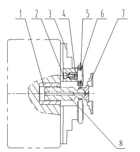
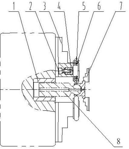
[0017] Attached below figure 1 Further description is given to specific embodiments of the present invention.

[0018] A plunger assembly rolling tool for lathes, including nylon guide sleeves, bolts, rolling chucks, connecting shafts, rollers, bearings and main clamping chucks; the rollers are basically ring-shaped and made of soft metal materials For example, low-carbon steel, the rolling surface is preferably a convex surface, and a groove is provided on the annular inner wall, and the outer ring of the bearing is pressed into the groove of the roller; the rolling chuck includes rolling claws, and the rolling chuck The claw is movably set on the base of the rolling chuck, and it can move along the radial direction of the rolling chuck, that is, change its position in the center of the rolling chuck; the connecting shaft acts as a connection, and one end is connected to the inner hole of the bearing It is connected in the way of interference fit, and the other end is fixed ...


PUM


Abstract

The invention provides a plunger assembly rolling and loosening fixture comprising a nylon guide sleeve, a bolt, a rolling and loosening chuck, a connecting shaft, an idler wheel, a bearing and a main clamping chuck. The idler wheel is circular, its circular internal wall is provided with a slot, outer ring of the bearing is pressed into the slot of the idler wheel. The rolling and loosening chuck comprises a rolling and loosening claw which can move radially along the rolling and loosening chuck. One end of the connecting shaft is in interference fit with internal hole of the bearing, and the other end is fixed on the rolling and loosening claw by the bolt. The nylon guide sleeve is circular and fixed in internal hole of the lathe chuck and coaxial with the internal hole. The main clamping chuck comprises a taper shank and multiple claws. The taper shank is fixed on rear seat of the lathe. The clamping faces of the claw are made of resin.

Description

technical field [0001] The invention relates to a rolling tool, in particular to a rolling tool used for a plunger assembly of a plunger pump or a hydraulic motor. Background technique [0002] The plunger assembly is the key part of the plunger pump and hydraulic motor. The plunger assembly is to match the inner and outer balls of the sliding shoe and the plunger body together. The cylinder of the sliding shoe is plastically deformed by crimping the tooling, and the outer ball of the plunger body is Included, thereby connecting the plunger body and the plunger seat together. After closing in this way, the sliding shoe and the plunger body cannot rotate flexibly, and it is necessary to go through a rolling process to make it flexibly rotate. The traditional loosening is generally carried out on a lathe. During processing, the product is clamped with soft jaws, and the rolling roller is installed on the tool holder. The roller is pressed on the plunger seat until it rotates ...

Claims


Application Information

Patent Timeline
IPC IPC(8): B23P19/10
Inventor 杨军华魏茂新黄福利孙同振张洪德
Owner SHANDONG CHANGLIN MACHINERY GRP
Features
  • R&D
  • Intellectual Property
  • Life Sciences
  • Materials
  • Tech Scout
  • Unparalleled Data Quality
  • Higher Quality Content
  • 60% Fewer Hallucinations
Learn More