Bypass type double-throat passive vectoring sprayer nozzle

A technology of vector nozzle and double throat, which is applied in the field of bypass double throat passive vector nozzle to achieve the effect of small flow loss and simple structure

Inactive Publication Date: 2012-05-02
NANJING UNIV OF AERONAUTICS & ASTRONAUTICS +1
View PDF3 Cites 34 Cited by
  • Summary
  • Abstract
  • Description
  • Claims
  • Application Information

AI Technical Summary

Problems solved by technology

The introduction of the secondary flow of the dual-throat aerodynamic vectoring nozzle with conventional active secondary jets is generally 3%-10% of the main flow, and requires a high-pressure air source (usually fr

Method used


Image

  • Bypass type double-throat passive vectoring sprayer nozzle
  • Bypass type double-throat passive vectoring sprayer nozzle
  • Bypass type double-throat passive vectoring sprayer nozzle

Examples


Embodiment 1

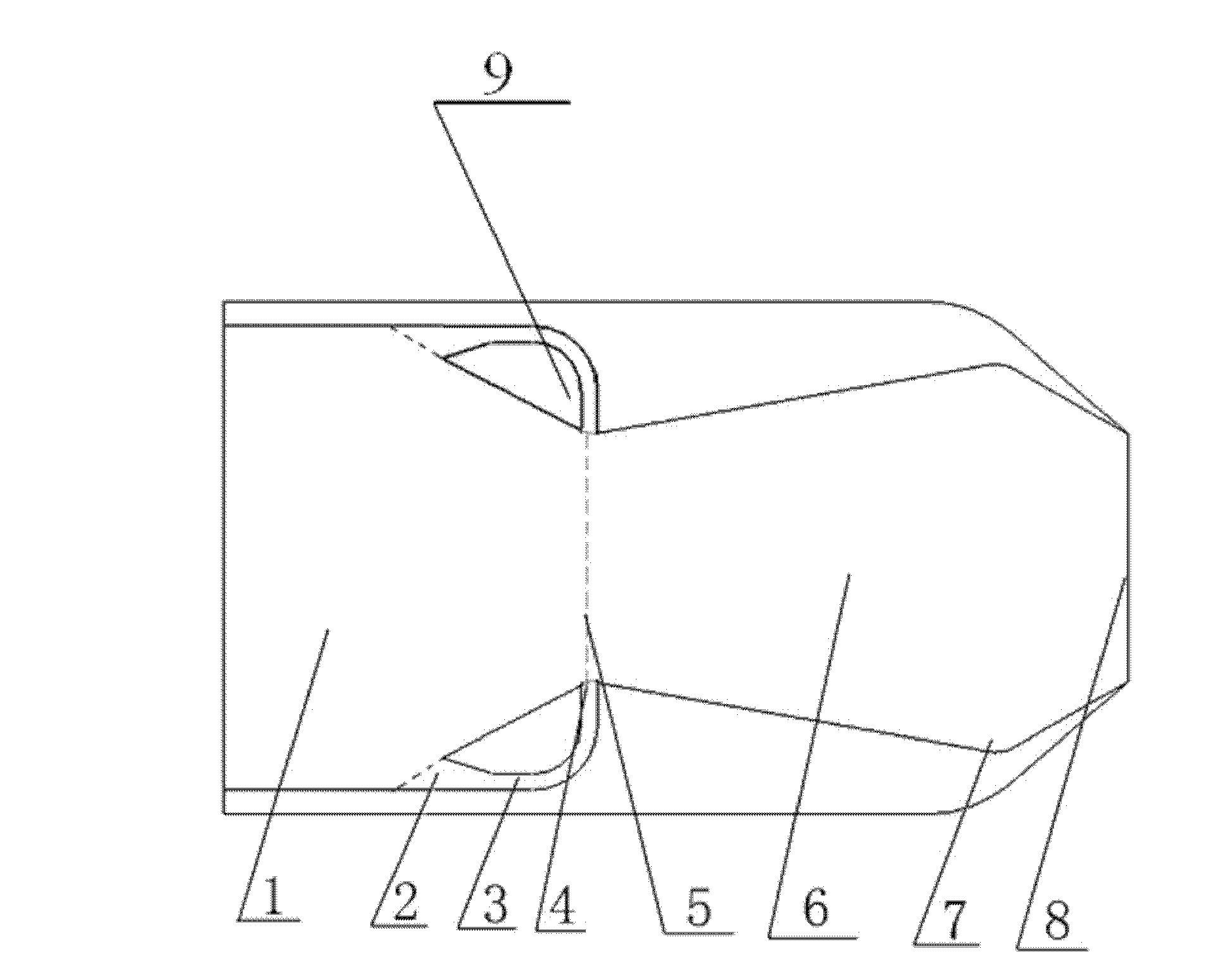
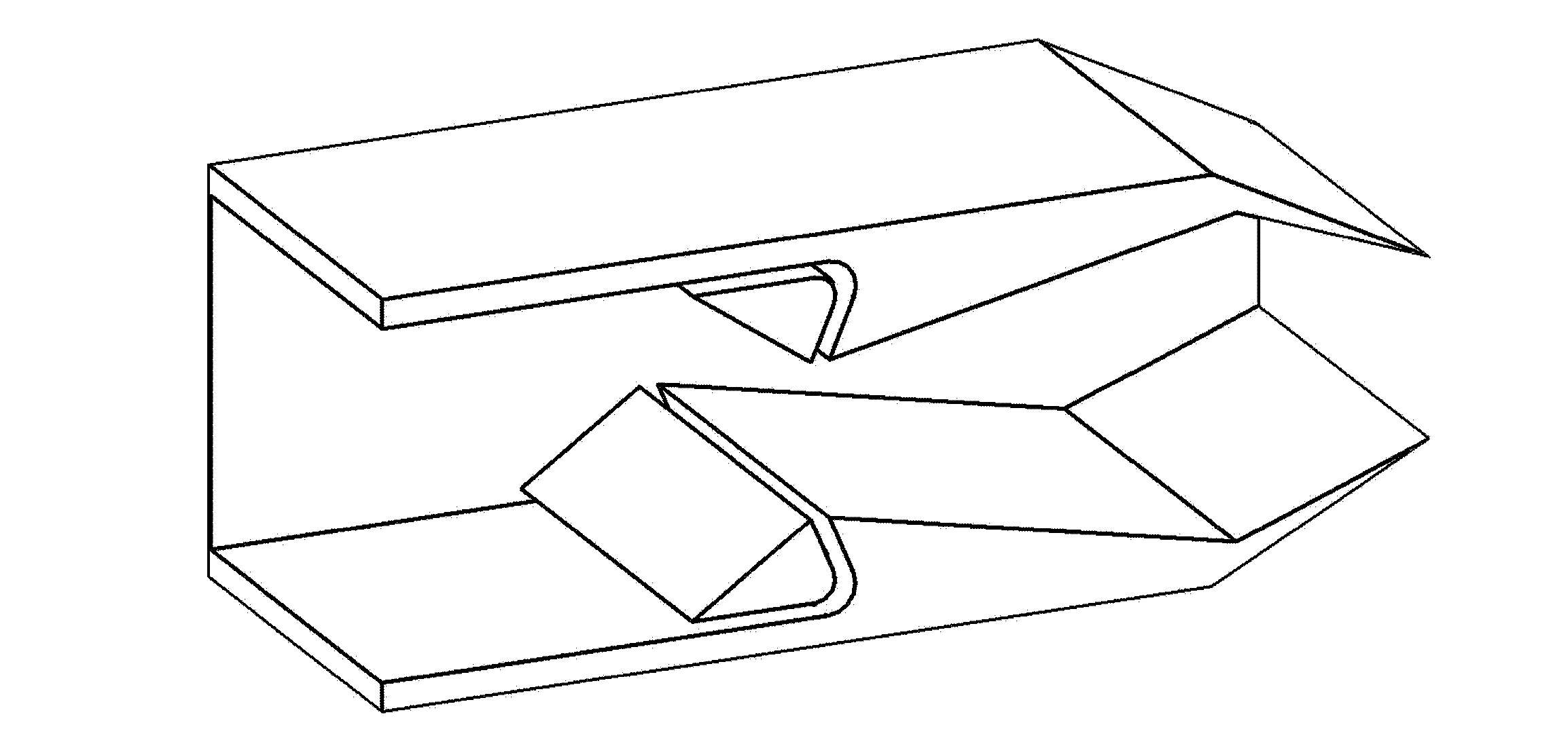
[0019] like figure 1 and figure 2 As shown, it is a schematic diagram of the structure of the present invention applied to the dual-throat nozzle. The present invention adds a bypass channel system to the existing dual-throat nozzle, which is the present invention. The bypass type double-throat passive vector nozzle includes a nozzle body, and the inner flow path of the nozzle body includes a converging section at the front of the throat, a throat, an expanding and converging section at the front of the second throat, Throat cavity and two throats, the converging section at the front of the throat is provided with a bypass channel adjacent to a throat, and the bypass channel is formed by a bypass projection transversely arranged in the inner flow channel of the nozzle body, The two end faces of the bypass projection perpendicular to the axis of the nozzle body are respectively welded and fixed to the inner channel of the nozzle body; the inlet of the bypass channel is arrang...

Embodiment 2

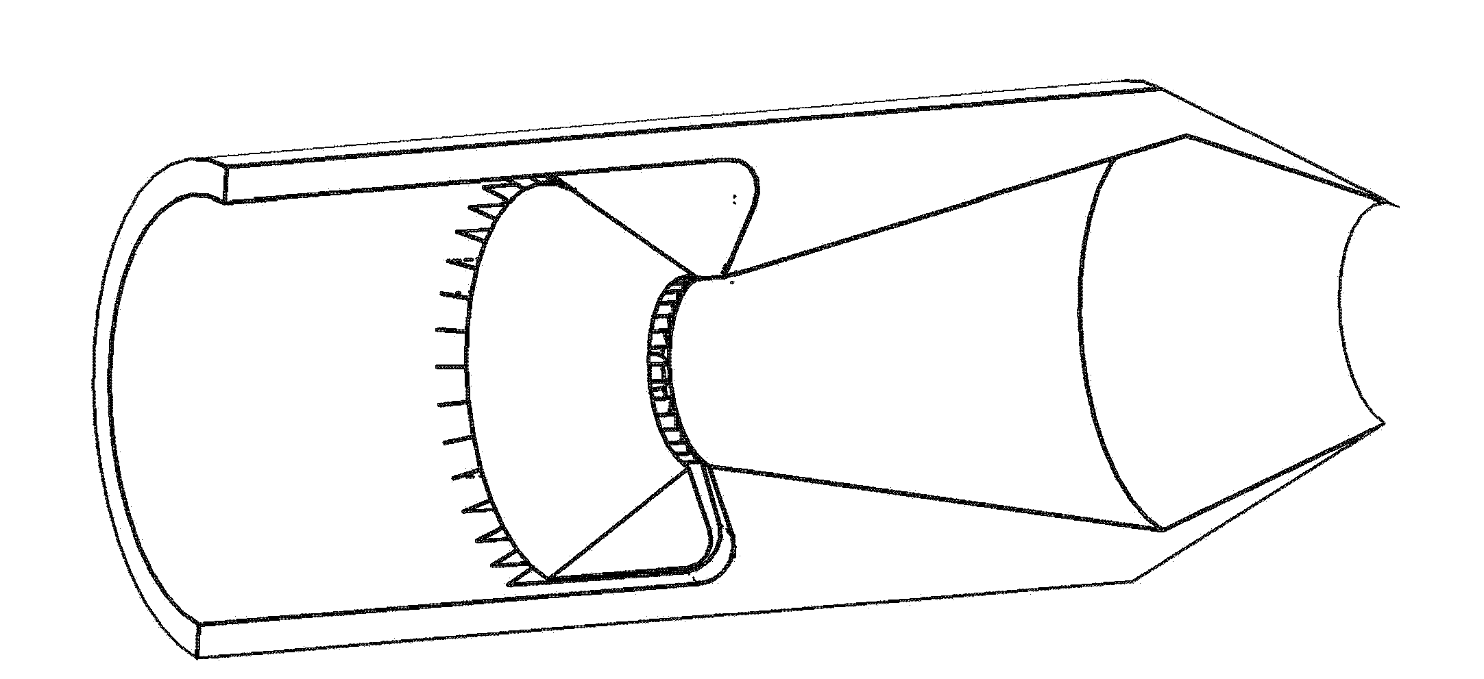
[0024] like figure 1 and 3 As shown, it is a structural schematic diagram of the present invention applied to an axisymmetric double-throat nozzle. The present invention adds a bypass passage system to the existing axisymmetric double-throat nozzle. The installation position, the height of the inlet of the bypass channel, the height and width of the outlet of the bypass channel, and the axial length of the bypass channel are all consistent with those in Embodiment 1. Only the way of forming the bypass channel in this embodiment is different from that in Embodiment 1. details as follows:

[0025] The present invention forms a bypass passage by arranging a bypass projection at a position close to a throat in the flow passage of the nozzle body. The interior of the bypass projection is provided with a flow passage along the axis, and the outer edge of the bypass projection is uniform in the circumferential direction. The protruding ribs are arranged, and the protruding ribs ar...


PUM


Abstract

The invention discloses a bypass type double-throat passive vectoring sprayer nozzle, comprising a sprayer nozzle main body, wherein the inner flow channel of the sprayer nozzle main body comprises front contraction sections of the throats, a bypass convex block, a first throat, a second throat front part expanded contraction section, throat reentrant cavities and a second throat; the front contraction sections of the throats are provided with bypass channels close to the first throat, wherein the inlets of the bypass channels are arranged facing the fluid entrance of the inner flow channel of the nozzle main body while the outlets of the bypass channels are arranged on the first throat. Therefore, the bypass channels are arranged in the double-throat nozzle to change the flow structure in the double-throat nozzle to further make the outflow of the nozzle achieve deviation, that is, producing and maintaining vector deflection. In addition, when the bypass type double-throat passive vectoring sprayer nozzle produces a thrust vector, a little flow loss is caused. The bypass type double-throat passive vectoring sprayer nozzle also has a simple structure, and does not influence performances of the nozzle when the nozzle works normally without vector deflections.

Description

technical field [0001] The invention relates to a bypass type double-throat passive vector nozzle, which is mainly used in all propulsion systems requiring vector thrust, such as thrust vector aero-engines and high-mobility missiles. Background technique [0002] With the development of science and technology, the demand for thrust vectoring of aero-engines is increasing. How to effectively generate vector thrust is a hot spot in the research of various countries. The introduction of the secondary flow of the dual-throat aerodynamic vector nozzle with conventional active secondary jet is generally 3%-10% of the main flow, and requires a high-pressure air source (usually bleed air from the compressor), even if the bleed air is not considered The loss caused by air to engine thrust, and only the design and layout of bleed air pipelines are also very complicated issues for aeroengines. Therefore, it is of great practical value to develop a passive vector nozzle with simple st...

Claims


Application Information

Patent Timeline
IPC IPC(8): F02K1/06F02K1/38
Inventor 李明徐惊雷黄顺洲顾瑞廖华琳伏宇莫建伟于洋
Owner NANJING UNIV OF AERONAUTICS & ASTRONAUTICS
Why Eureka
Try Eureka