
Hydraulic cylinder sealing structure

A sealing structure and hydraulic cylinder technology, applied in the direction of engine sealing, engine components, mechanical equipment, etc., can solve problems such as difficult guide ring 3' replacement and disassembly, guide ring 3' wear, limited effective support length, etc., to improve Effective support length, not easy to wear, easy to replace and install

Active Publication Date: 2012-05-02
HUNAN TELI HYDRAULIC
View PDF12 Cites 12 Cited by
  • Summary
  • Abstract
  • Description
  • Claims
  • Application Information

AI Technical Summary

Problems solved by technology

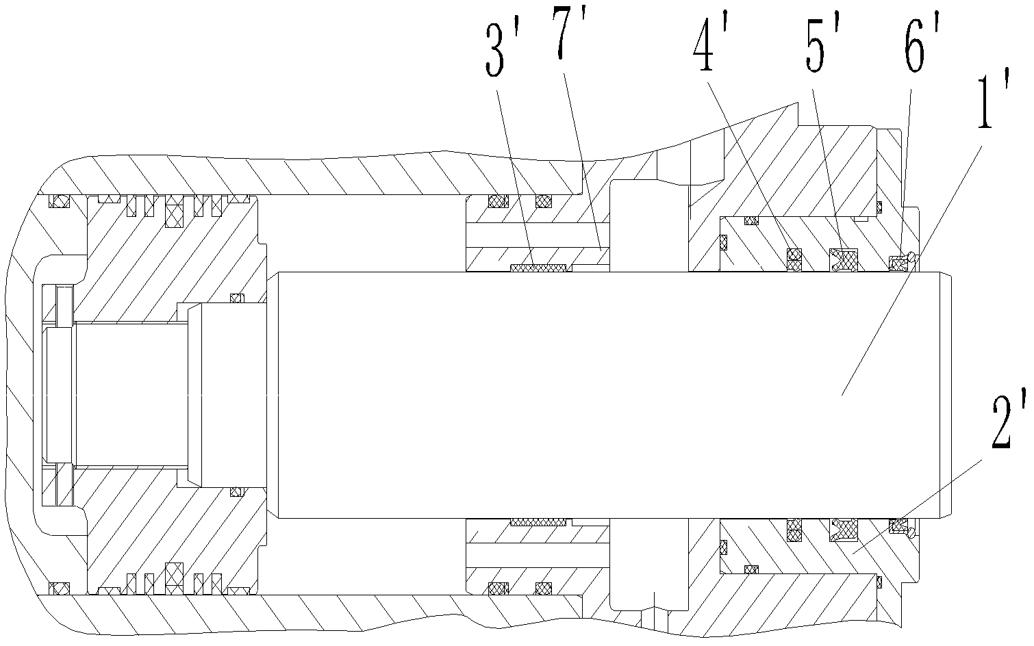
Wherein, the guide ring 3' is arranged in the guide sleeve 7'. When the piston rod 1' is stretched out, the effective support length of the guide ring 3' to the piston rod 1' is limited, and since the guide ring 3' is located in the middle of the hydraulic cylinder, It is not easy to replace and disassemble the guide ring 3' In addition, if image 3 As shown, under normal circumstances, the inner surface of the guide ring 3' used to guide the piston rod 1' remains attached to the piston rod 1', but once the piston rod 1' tilts, the guide ring 3 'The inner surface of the piston rod 1' cannot continue to be in contact with the piston rod 1', and the piston rod 1' is very easy to cause wear to the guide ring 3'

Method used


Image

  • Hydraulic cylinder sealing structure
  • Hydraulic cylinder sealing structure
  • Hydraulic cylinder sealing structure

Examples


Embodiment Construction

[0035] Specific embodiments of the present invention will be described in detail below with reference to the accompanying drawings.

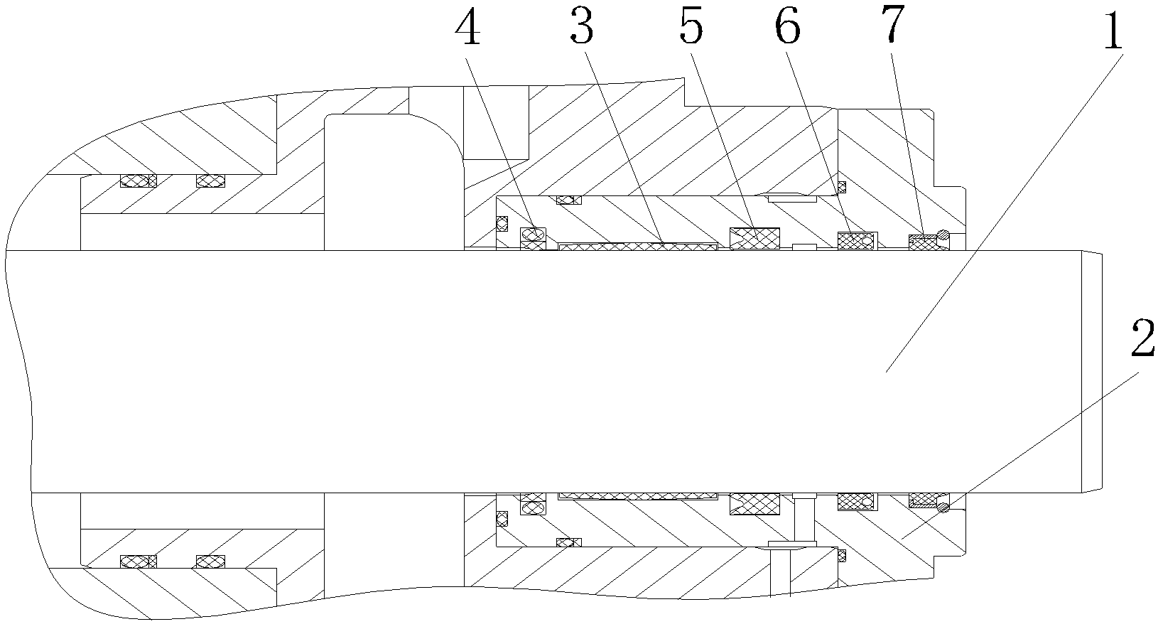
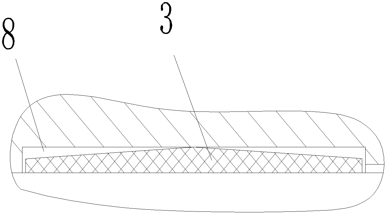
[0036] figure 1 is a cross-sectional view of the hydraulic cylinder sealing structure of the present invention, figure 2 for figure 1 A partially enlarged view of the guide ring in the sealing structure of the hydraulic cylinder of the present invention.

[0037] The invention provides a hydraulic cylinder sealing structure, such as figure 1 As shown, the sealing structure includes a guide ring 3 and a guide part 2 arranged at the end of the hydraulic cylinder. A groove 8 is formed on the inner wall of the guide part 2. The guide ring 3 is arranged in the groove 8 and the inner surface is attached to the on piston rod 1.

[0038] Different from the sealing structure of the hydraulic cylinder in the prior art, the guide ring 3 of the present invention is directly arranged at the end of the entire hydraulic cylinder, rather than at the mid...


PUM


Abstract

The invention provides a hydraulic cylinder sealing structure, which comprises a guide ring (3) and a guide part (2) disposed close to the end of a hydraulic cylinder. A groove (8) is formed on the inner wall of the guide part (2), the guide ring (3) is arranged in the groove (8), and the internal surface of the guide ring (3) is attached to a piston rod (1). The position of the guide ring is moved backwards from the middle of the hydraulic cylinder to the end of the hydraulic cylinder so that effective support length of the guide ring toward the piston rod is prolonged and the guide ring is led to be easier to demount, replace and install.

Description

technical field [0001] The invention relates to a sealing structure, more specifically, to a sealing structure applied to a hydraulic cylinder. Background technique [0002] A hydraulic cylinder is an energy conversion device that converts hydraulic energy into mechanical energy. It is an actuator in a hydraulic system and is generally used to achieve reciprocating linear motion or swing. [0003] The sealing of the hydraulic cylinder mainly refers to the sealing between the piston and the cylinder body, the piston rod and the end cover, and between the cylinder body and the end cover. The quality of the sealing performance will directly affect its working performance and efficiency. Therefore, the hydraulic cylinder is required to have good sealing performance under a certain working pressure, and the sealing performance should be automatically enhanced with the increase of the working pressure. In addition, the sealing element is also required to have the advantages of s...

Claims


Application Information

Patent Timeline
Patent Type & Authority Applications(China)
IPC IPC(8): F16J15/16F16J15/18
Inventor 唐刚明张建森胡帮明
Owner HUNAN TELI HYDRAULIC
Learn More