Boost power factor correction (PFC) controller

A controller and boost-type technology, applied in sustainable manufacturing/processing, high-efficiency power electronic conversion, output power conversion devices, etc., can solve the problems of high difficulty and high design cost, achieve less peripheral components, and reduce design difficulty , the effect of fewer pins

Active Publication Date: 2012-05-02
SILERGY SEMICON TECH (HANGZHOU) CO LTD
View PDF4 Cites 30 Cited by
  • Summary
  • Abstract
  • Description
  • Claims
  • Application Information

AI Technical Summary

Problems solved by technology

In the PWM controller of this traditional CCM step-up PFC circuit, an oscillator needs to be built in to generate a sawtooth wave signal with a fixed clock frequency, so as to ensure that the power switch tube Q M The operating frequency is constant; in addition, in th

Method used


Image

  • Boost power factor correction (PFC) controller
  • Boost power factor correction (PFC) controller
  • Boost power factor correction (PFC) controller

Examples


Embodiment Construction

[0032] Preferred embodiments of the present invention will be described in detail below with reference to the accompanying drawings, but the present invention is not limited to these embodiments. The present invention covers any alternatives, modifications, equivalent methods and schemes made on the spirit and scope of the present invention. In order to provide the public with a thorough understanding of the present invention, specific details are set forth in the following preferred embodiments of the present invention, but those skilled in the art can fully understand the present invention without the description of these details.

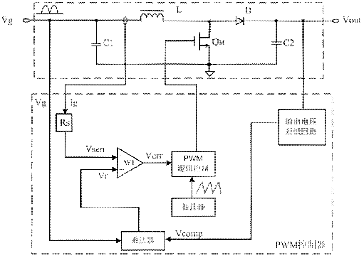
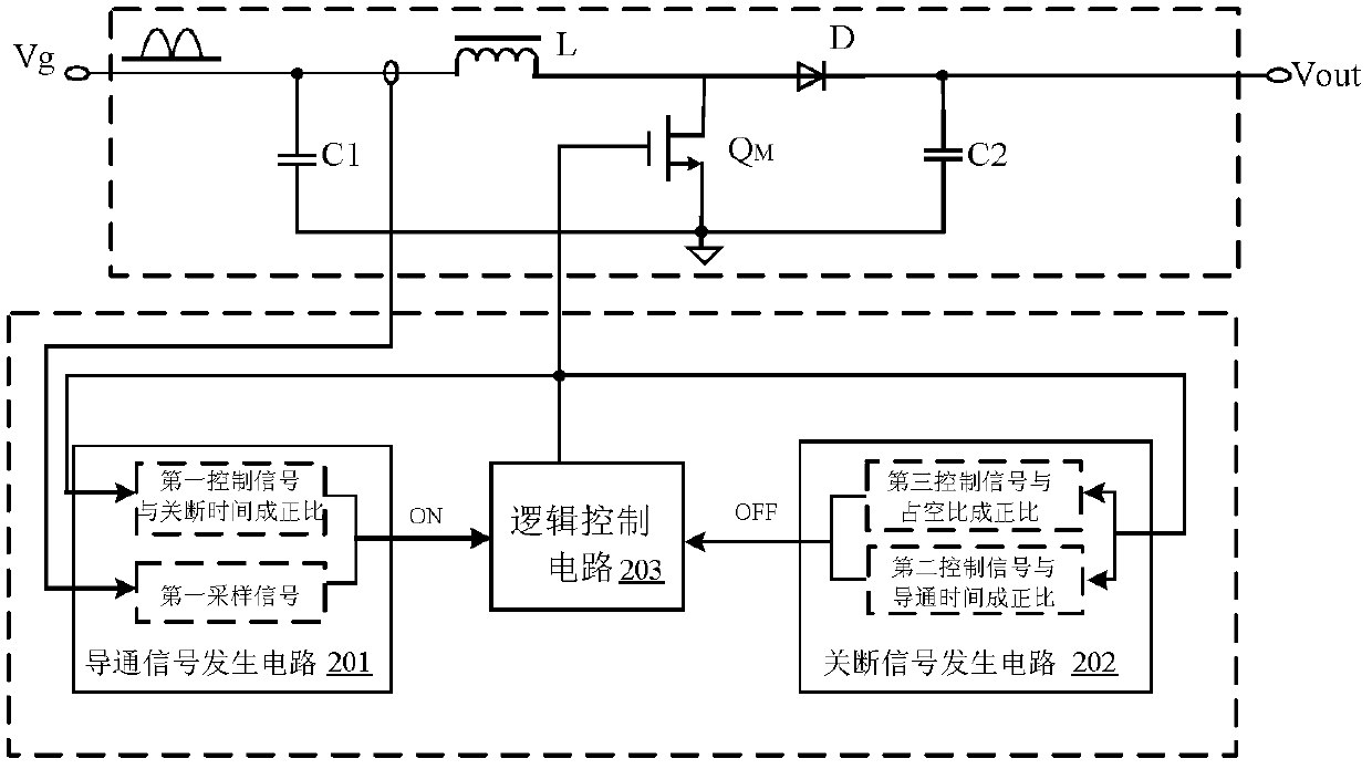
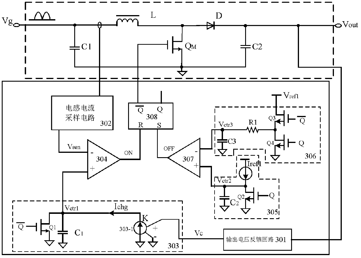
[0033] A step-up PFC controller described in the present invention is applied in an AC / DC converter, and the AC / DC converter also includes a power stage circuit, which has been introduced in the background technology, and the following implementations The components in the power stage circuit in the example are the same as those in the background...


PUM


Abstract

The invention discloses a boost power factor correction (PFC) controller. The switching-on and switching-off of a power switching tube are controlled by switching on and switching off a signal generation circuit, so that the power switching tube is controlled to operate in a constant-frequency or variable-frequency mode. Therefore, when the boost PFC controller is used, the constant operating frequency of the power switching tube can be realized without control of a clock signal, so that the design difficulty of an input electro-magnetic interference (EMI) filter is reduced; moreover, the boost PFC controller can control the variation range of the operating frequency of the power switching tube. Compared with the conventional switching frequency jittering control technology, the invention has the advantages that: the boost PFC controller is quite convenient and has simple control scheme; frequency jittering operation can be realized; meanwhile, in the process of realizing PFC, the waveform of an input voltage is not required to be detected; the number of controller pins and peripheral devices is smaller; and cost is reduced.

Description

technical field [0001] The invention relates to the field of power factor correction, and more specifically, relates to a step-up PFC controller. Background technique [0002] In order to reduce the harmonic pollution caused by power electronic devices to the power grid, a power factor correction (PFC) circuit is usually added to its input side. At present, an active power factor correction circuit is often used to convert the input current of power electronic devices to the input voltage. The sine wave with the same phase is used to improve the power factor of the power electronic device, so as to reduce the harmonic pollution of the power grid. At present, the active PFC circuit often adopts the boost PFC circuit topology. In high-power applications, the step-up PFC circuit of continuous conduction mode (CCM) is more attractive, the following reference figure 1 A typical CCM step-up PFC circuit is described. [0003] refer to figure 1 , shows a typical CCM step-up PFC c...

Claims


Application Information

Patent Timeline
IPC IPC(8): H02M1/42H02M1/08
CPCY02B70/126H02M1/42H02M1/4225Y02B70/10Y02P80/10
Inventor 赵晨姚杰
Owner SILERGY SEMICON TECH (HANGZHOU) CO LTD
Why Eureka
Try Eureka