
Generator, nacelle, and mounting method of a nacelle of a wind energy converter

A generator and wind energy technology, applied in wind energy power generation, wind turbine components, wind turbines in the same direction as the wind, etc., can solve problems such as complexity and difficult tasks, and achieve the effects of improving heating, reducing costs, and reducing total costs.

Active Publication Date: 2012-05-02
美国超导奥地利有限公司
View PDF8 Cites 8 Cited by
  • Summary
  • Abstract
  • Description
  • Claims
  • Application Information

AI Technical Summary

Problems solved by technology

This task is difficult and complex due to the size and weight of these components

Method used


Image

  • Generator, nacelle, and mounting method of a nacelle of a wind energy converter
  • Generator, nacelle, and mounting method of a nacelle of a wind energy converter
  • Generator, nacelle, and mounting method of a nacelle of a wind energy converter

Examples


Embodiment Construction

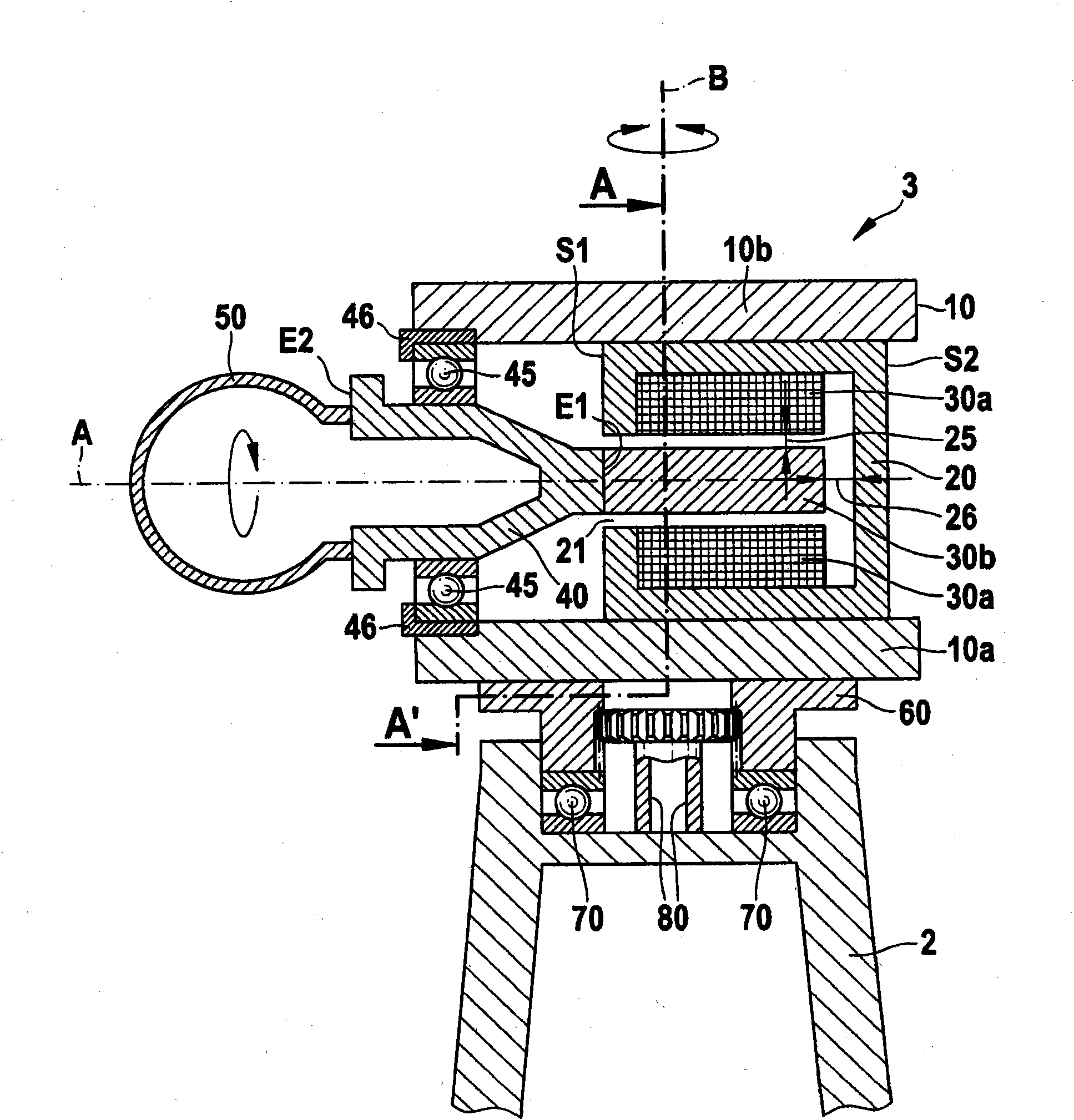
[0049] Figure 5 is a side view showing an example of the overall structure of the wind energy converter. The wind energy converter 1 comprises: a tower 2 arranged on a foundation 6; a nacelle 3 arranged on the upper end of the tower 2, the nacelle 3 being able to rotate about a substantially vertical axis B; and a rotor head arranged on the nacelle 3 The rotor head 4 includes a hub (not shown) for fixing the rotor blades 5, and the rotor head 4 is rotatable about a substantially horizontal axis A.

[0050] Blades 5 extending radially from the axis of rotation A are attached to the rotor head 4 at different circumferential angles. Wind force supplied to the blades 5 from the direction of the variable axis of rotation A of the rotor head 4 causes the rotor head 4 to rotate about its axis of rotation.

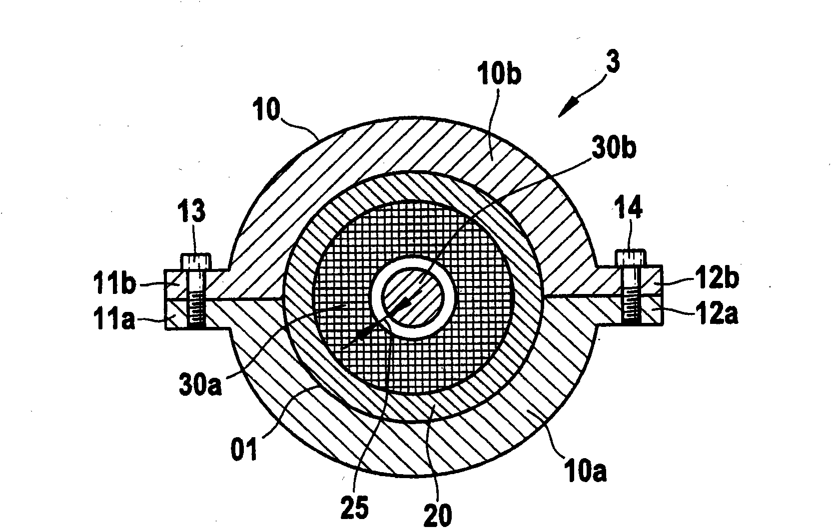
[0051] Figure 1a and 1b is a cross-sectional view showing an example of the internal structure of the nacelle, where, Figure 1a Middle is a longitudinal section along the ax...


PUM


Abstract

An apparatus for wind energy conversion includes a nacelle having a main frame, the main frame having a lower part and an upper part joined to the lower part, the upper part having a first strap extending across the lower part; a stator disposed within the nacelle; a rotor disposed within the nacelle; a mounting surface attached to the main frame and defining a rotor space, the mounting surface having a first side-face that exposes the rotor space; and a flange rotatably supported on the main frame and including a first end connected to the rotor. The rotor is cantilevered from the flange into the rotor space from the first side face.

Description

technical field [0001] The present disclosure relates generally to wind energy converters and in particular to generators, nacelles and installations to the nacelles of wind energy converters. Background technique [0002] A wind energy converter is a rotating machine that converts the kinetic energy in the wind into electricity and supplies the electricity to the grid. [0003] A wind energy converter usually includes a nacelle arranged on a tower. The nacelle (also called "pod") comprises a rotor head equipped with blades and a main shaft, also called hub, connected to the rotor head, which shaft rotates integrally with the rotor head. In addition, the nacelle can be rotated about a vertical axis to actively or passively follow the direction of the wind. [0004] The first nacelle also includes a gearbox connected to a main shaft that rotates when receiving wind power supplied to the blades and a generator driven by an output shaft from the gearbox. According to the win...

Claims


Application Information

Patent Timeline
Patent Type & Authority Applications(China)
IPC IPC(8): F03D11/00F03D9/00F03D1/00
CPCH02K7/1838Y02E10/725F05B2220/7066Y02E10/722F03D9/002F03D1/001Y02E10/72Y02E10/726H02K5/1735H02K7/183F03D11/0008Y02E10/728F03D80/70F03D9/25F03D13/10Y10T29/49009F03D80/80F03D80/60F03D13/20F03D1/00H02K7/18
Inventor 马丁·菲舍尔安东·沃尔夫迈克尔·施瓦茨
Owner 美国超导奥地利有限公司
Learn More