Three-dimensional cutting machining method

A cutting and three-dimensional technology, applied in metal processing, metal processing equipment, metal processing mechanical parts, etc., can solve the problem of inability to correct the error of the processing position, and achieve the effect of high-precision correction

Active Publication Date: 2012-05-09
CHANGZHOU NALUX OPTICS
View PDF5 Cites 5 Cited by
  • Summary
  • Abstract
  • Description
  • Claims
  • Application Information

AI Technical Summary

Problems solved by technology

Therefore, for a processing object whose cross-sectional shape is a complex shape including local extreme values, the processing position due to tool bending cannot be corrected by adding a correction term that expresses the lens surface from a constant to a polynomial. error

Method used


Image

  • Three-dimensional cutting machining method
  • Three-dimensional cutting machining method
  • Three-dimensional cutting machining method

Examples


Embodiment Construction

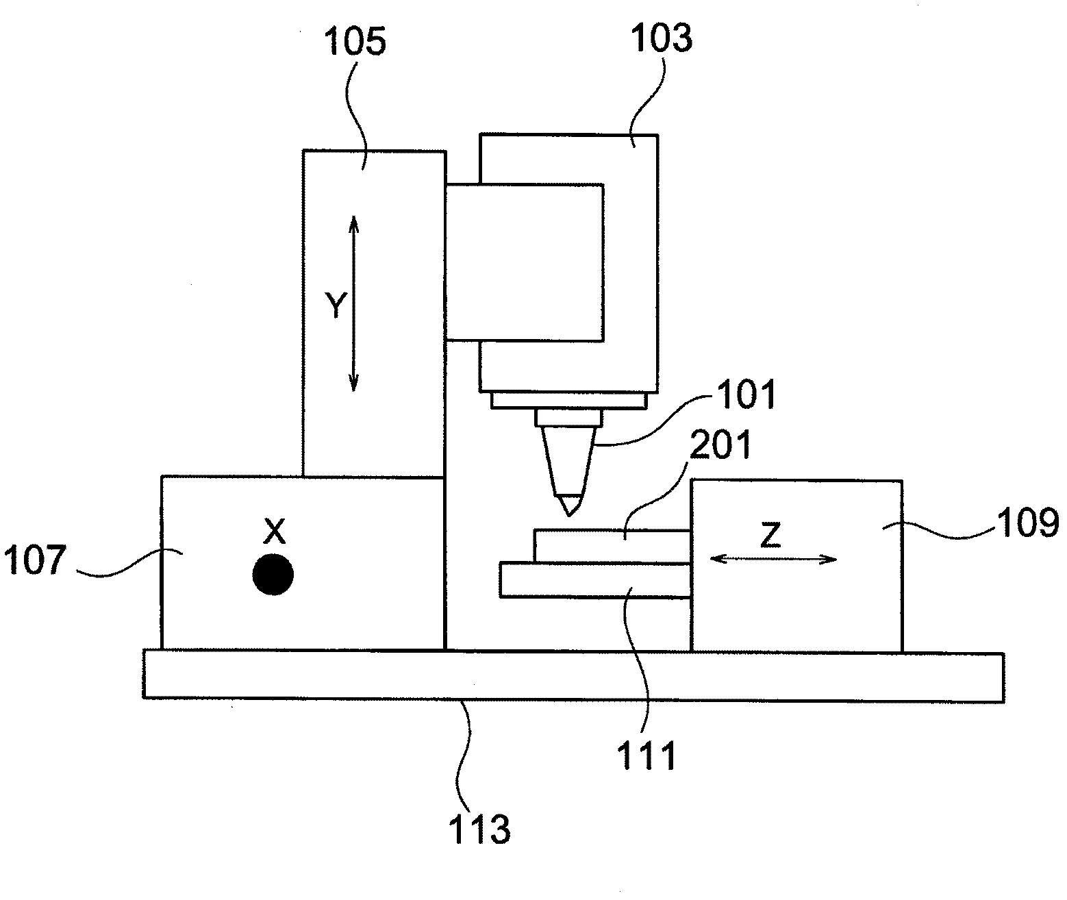
[0038] See figure 1 , the tool 101 of the three-dimensional cutting machine in the present invention is installed on the lifting platform 103 . The lift table 103 is mounted on a base 105 movable in the Y-axis direction (vertical direction). The base 105 is mounted on an X-axis direction moving stage 107 that can move in the X-axis direction. On the other hand, the job 201 is held and sucked on the table 111 by a vacuum fastener or the like. The stage 111 is fixed on a Z-axis direction movable table 109 that can move in the Z-axis direction.

[0039] exist figure 1 In the shown three-dimensional cutting machine, the elevating table 103, the X-axis direction moving table 107, and the Z-axis direction moving table 109 are each configured to be movable in the Y-axis direction, the X-axis direction, and the Z-axis direction. The work held on the movable table moving in the Z-axis direction, as another component of the three-dimensional cutting machine, can be applied to the pr...


PUM


Abstract

The invention relates to a machining method in the field of machinery, in particular to a three-dimensional cutting machining method for mould machining of optical articles. By the three-dimensional cutting machining method, the position of a tool is corrected by using a more accurate correction term, and the machining precision is higher. In the three-dimensional cutting machining method, an object is machined by a tool which is installed on a central rotating shaft according to designed machining track, wherein the machining position of the tool is a curvilinear coordinate (r, theta) which takes a point on the central rotating shaft as an original point; the position coordinate of the tool is provided with a correction term; the correction term is in direct proportion with sin (2phi); and phi is the included angle between a tangent of the tool to a machining plane to which a working machining point belongs and the horizontal plane. By the three-dimensional cutting machining method, the error of a machining position due to bending of the tool is effectively reduced.

Description

technical field [0001] The invention relates to a machining method in the mechanical field, in particular to a three-dimensional cutting method for mold processing of optical articles. Background technique [0002] A three-dimensional cutting machine performs processing while changing the three-dimensional cutting position coordinates (hereinafter referred to as the offset printing position) of the center shaft tool to realize the expected processing surface. For example, there is related introduction. Optical component molds have extremely high precision requirements, and ordinary three-dimensional processing methods cannot meet the precision requirements. [0003] When any three-dimensional processing is processing the processing object (hereinafter referred to as the operation), due to the reaction force of the operation on the tool, the tool itself will undergo elastic deformation (hereinafter referred to as bending), so the offset position of the tool will also change ...

Claims


Application Information

Patent Timeline
Patent Type & Authority Applications(China)
IPC IPC(8): B23Q15/00B23Q15/22
Inventor 大割宽向井幸弘槇宣志西尾幸暢
Owner CHANGZHOU NALUX OPTICS
Why Eureka
Try Eureka