Spray head cleaning device and working method thereof

A cleaning device and nozzle technology, applied in printing and other directions, can solve problems such as poor cleaning effect, and achieve the effect of overcoming poor cleaning effect, saving costs and improving cleaning effect

Inactive Publication Date: 2012-05-09
PEKING UNIV FOUNDER GRP CO LTD +2
View PDF11 Cites 19 Cited by
  • Summary
  • Abstract
  • Description
  • Claims
  • Application Information

AI Technical Summary

Problems solved by technology

[0005] The present invention aims to provide a nozzle cleaning device and its working meth

Method used


Image

  • Spray head cleaning device and working method thereof
  • Spray head cleaning device and working method thereof
  • Spray head cleaning device and working method thereof

Examples


Embodiment Construction

[0013] The present invention will be described in detail below with reference to the accompanying drawings and in combination with embodiments.

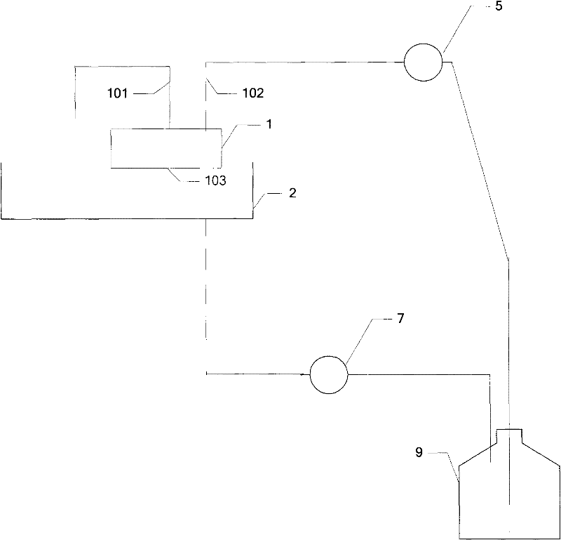
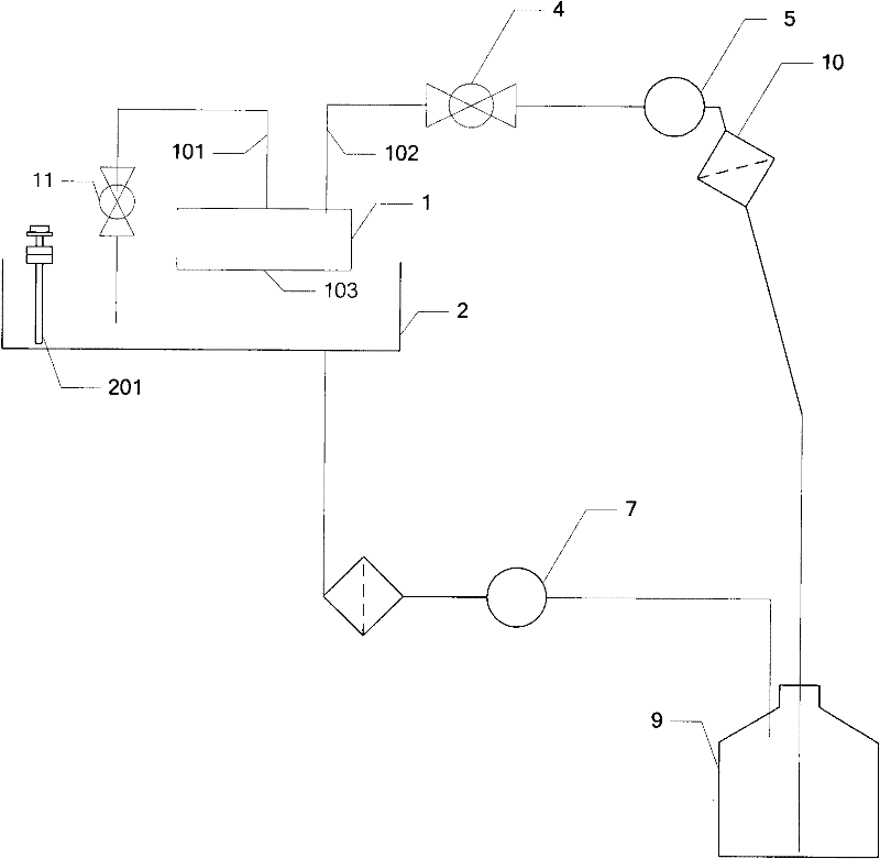
[0014] figure 1 A structural diagram of a nozzle cleaning device according to an embodiment of the present invention is shown, including:

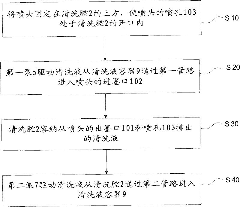
[0015] The first pipeline is used to connect the ink inlet 102 of the nozzle to the cleaning liquid container 9;

[0016] The first pump 5 is arranged in the first pipeline, and is used to drive the cleaning liquid from the cleaning liquid container 9 to enter the ink inlet 102 through the first pipeline;

[0017] The cleaning chamber 2 is used to support the print head and accommodate the cleaning liquid discharged from the ink outlet 101 and the nozzle hole 103 of the print head;

[0018] The second pipeline is used to connect the cleaning chamber 2 and the cleaning solution container 9;

[0019] The second pump 7 is arranged in the second pipeline, and is used to drive the cleaning liquid f...


PUM


Abstract

The invention provides a spray head cleaning device and a working method thereof. The device comprises a first pipeline, a first pump, a cleaning cavity, a second pipeline and a second pump, wherein the first pipeline is used for connecting an ink inlet of a spray head to a cleaning solution container; the first pump is arranged in the first pipeline and used for driving cleaning solution to enter the ink inlet from the cleaning solution container through the first pipeline; the cleaning cavity is used for supporting the spray head and containing the cleaning solution discharged from the ink inlet and a spray hole of the spray head; the second pipeline is used for connecting the cleaning cavity to the cleaning solution container; and the second pump is arranged in the second pipeline and used for driving the cleaning solution to enter the cleaning solution container from the cleaning cavity through the second pipeline. According to the spray head cleaning device and a working method thereof disclosed by the invention, the purpose of increasing the cleaning effect of the spray head is achieved, thus, the cost of ink jet printing equipment is saved.

Description

technical field [0001] The invention relates to the printing field, in particular to a nozzle cleaning device and a working method thereof. Background technique [0002] Digital inkjet printing has a wide range of applications in the fields of personalized short-board printing and variable data printing. The printhead is currently a relatively expensive and fragile component in an inkjet printer. During the use of the nozzle, the nozzle holes are prone to clogging, and some stubborn clogging holes are difficult to remove in a short time. [0003] At present, the clogging of the nozzles is mostly caused by the solidification of the surface ink and other impurities attached to the surface of the nozzles. The current cleaning method is to complete the on-line cleaning of the nozzles through the circulation of the cleaning liquid, which can solve the problem of some nozzle clogging, but for dry ink, etc. Stubborn holes are difficult to remove by this method. [0004] The prio...

Claims


Application Information

Patent Timeline
IPC IPC(8): B41J2/165
Inventor 关书靖邢笑笑陈峰刘志红
Owner PEKING UNIV FOUNDER GRP CO LTD
Why Eureka
Try Eureka