Central control brake system and trolley type movable medical equipment

A central control and braking system technology, which is applied to hospital equipment, trolleys, trolley accessories, etc., can solve the problems of inconvenient and laborious operation, and achieve the effect of convenient operation and labor saving

Active Publication Date: 2012-05-09
SHENZHEN MINDRAY BIO MEDICAL ELECTRONICS CO LTD
View PDF6 Cites 16 Cited by
  • Summary
  • Abstract
  • Description
  • Claims
  • Application Information

AI Technical Summary

Problems solved by technology

[0004] The main technical problem to be solved by the present invention is to overcome the problems of inconvenient and laborious operation of the existing central control braking system, and provide an easy-to-operate central control braking system

Method used


Image

  • Central control brake system and trolley type movable medical equipment
  • Central control brake system and trolley type movable medical equipment
  • Central control brake system and trolley type movable medical equipment

Examples


Embodiment 1

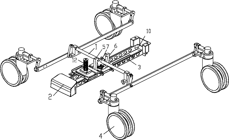
[0031] Please refer to Figure 1 to Figure 3 , The central control brake system of the present embodiment includes a base frame (not shown in the figure), castors 4, brake transmission shaft 1, plate beam 3, pedal 2 and reversing transmission assembly. Wherein, the base frame is connected with the car body, the plate beam 3 and the casters 4 are installed at the bottom of the base frame, and the plate beam 3 is movably connected with the base frame, the pedal 2 is fixed on the plate beam 3, and the reversing rotating assembly connects the plate beam 3 and The brake rotation shaft 1 is used to make the brake drive shaft 1 reversing and rotate under the control of the pedal 2 . The number of casters 4 can be one or more, and the brake transmission shaft 1 is connected with the casters 4 using a connecting rod structure. When the brake transmission shaft 1 rotates forward or reverse under the drive of the reversing rotating assembly, the brakes of the casters 4 are respectively c...

Embodiment 2

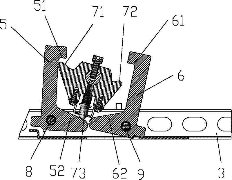
[0035] Please refer to image 3 and Figure 4The upper end of the first reversing hook 5 is provided with a first snapping hook 51, and the lower end is provided with a first resisting portion 52 on the same side as the first snapping hook 51. Correspondingly, the upper end of the second reversing hook 6 is provided with a second snapping hook. Hook 61, the lower end is provided with the second abutting portion 62 on the same side as the second snapping hook 61; The bottom is provided with telescoping rod 73. Before the operator depresses the pedal 2, the reversing rotation assembly is in the first relative position, and the telescopic rod 73 is against the top of the first resisting portion 52. When the operator depresses the pedal 2 and moves it downward for a certain distance, the first reversing member The first engaging hook 51 on the hook 5 engages with the first engaging part 71 on the reversing wheel 7 and rotates synchronously. When the operator releases the pedal 2...

Embodiment 3

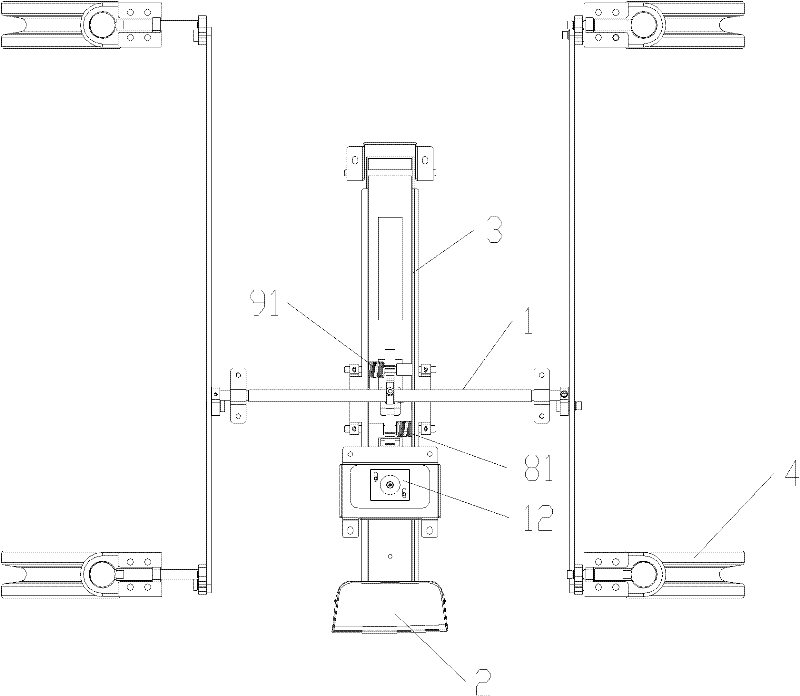
[0041] The connection mode between the plate girder 3 and the base frame, and the positions of the pedal 2, the first reversing hook 5 and the second reversing hook 6 on the plate girder 3 can be determined according to requirements. Figure 5 In the illustrated embodiment, one end of the plate girder 3 is rotatably connected to the base frame through the base frame rotating shaft 10, the other end is fixed to the pedal 2, and the first reversing hook 5 and the second reversing hook 6 are rotatably connected to the middle part of the plate girder 3. The plate girder 3 is relatively long. When the operator steps on the pedal 2, the entire plate girder 3 drives the reversing wheel 7 to rotate a certain angle through the first reversing hook 5 or the second reversing hook 6, so that the pedal 3 can be turned downward. Move a larger distance to realize the conversion of the reversing rotating assembly to different states. Therefore, the motion track of the pedal 2 is close to a str...


PUM


Abstract

The invention discloses a central control brake system and trolley type movable medical equipment. The central control brake system comprises a base frame, at least one trundle (4), a brake transmission shaft (1), a plate beam (3), a pedal (2) and a deflecting rotary component. The brake transmission shaft (1) is used for controlling the trundles (4) which are mounted at the bottom of the base frame. The pedal (2) is fixed onto the plate beam (3) which is movably connected with the base frame, and the deflecting rotary component is connected with the plate beam (3) and the brake transmission shaft (1) and drives the brake transmission shaft (1) to deflect and rotate under the control of the pedal (2). Braking and brake releasing of the trundles can be controlled by an operator via stepping on the pedal, and thereby operation is more convenient and laborsaving, and insteps of the operator cannot be hurt.

Description

technical field [0001] The invention belongs to the field of medical equipment, and in particular relates to a centrally controlled braking system and a cart-type movable medical equipment. Background technique [0002] The braking devices used for various types of movable medical equipment such as push beds and carts usually use a central control braking system. Compared with the traditional braking system that uses different braking mechanisms to control different casters, the central control braking system One brake mechanism is used to simultaneously control multiple casters to brake or release the brakes at the same time, which is more convenient to operate. The central control brake system includes a double-pedal brake system and a single-pedal brake system. The former uses one pedal to control the brake of the caster, and the other pedal controls the brake of the caster to release the brake; The casters brake when the pedal is lowered, and the casters release the bra...

Claims


Application Information

Patent Timeline
Patent Type & Authority Applications(China)
IPC IPC(8): B62B5/04
CPCB62B5/0433A61G7/1046A61G13/104A61G7/018A61G7/0528B60B33/0092
Inventor 陈绪贵胡敏周明钊
Owner SHENZHEN MINDRAY BIO MEDICAL ELECTRONICS CO LTD
Why Eureka
Try Eureka